
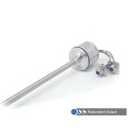
Series 13R redundant output mobile hydraulic magnetostrictive displacement sensor
Dual redundant output for safety-critical mobile hydraulic applications
Series 13R is the redundant output version of Series 13, with two fully independent measuring channels (Channel A + Channel B). A single permanent magnet acts on both measuring systems simultaneously, producing two independent position signals. It is intended for mobile machinery and mobile hydraulic equipment with extremely high safety and reliability requirements - if either channel fails, the other keeps working and the system stays online. IP68 protection (IP69K with dedicated M12x1 connector), vibration resistance 25 g and shock resistance 100 g suit the toughest construction machinery conditions. Stainless steel housing, -40°C to +85°C operating temperature range.
Product Overview
Series 13R is the safety redundant enhanced version of Series 13, designed for mobile hydraulic applications with extremely high reliability requirements. Two fully independent measuring channels operate in parallel as hot standbys for each other.
In safety-critical applications - such as crane boom angle monitoring, lift control on aerial work platforms and railway point machines - if either channel develops a fault, the other takes over immediately, ensuring the system neither stops nor runs out of control.
Shares the same compact form factor and IP68 / IP69K protection class as the Series 13C, with 25 g vibration resistance (10-2000 Hz) and 100 g shock resistance. The precision cast stainless steel housing is a perfect match for the dusty, heavily polluted and high-vibration conditions of construction machinery. Only 1 W power consumption per channel.
Operating Principle
Series 13R uses a dual-channel redundant magnetostrictive measuring architecture. Two independent waveguides and detection circuits are arranged in the same stainless steel pressure tube; a single external permanent magnet (position magnet) acts on both measuring systems simultaneously, each independently triggering the magnetostrictive effect and producing two fully independent position output signals. The dual-channel design ensures that a single component failure will not cause loss of position information, meeting the redundancy requirements of safety-critical applications. It shares the same mechanical structure and protection design as Series 13C, with only a second independent measuring channel added in the electronics module.
Typical Applications
Technical Specifications
| Measuring Range | 75 ~ 450 mm |
|---|---|
| Resolution | <500mm ±0.10mm, 700mm ±0.18mm, 1000mm ±0.24mm, 1250mm ±0.30mm, 1750mm ±0.42mm |
| Repeatability | < ±0.005% of full scale |
| Non-Linearity | < ±0.04% of full scale (min. ±100 µm in the 60 mm damping zone); < ±0.08% (36.5 mm damping zone) |
| Output Signal | Dual-channel redundant voltage / current output (Channel A + Channel B measure independently) |
| Supply Voltage | +12Vdc / +24Vdc |
| Input Protection | Reverse polarity protection to -30 Vdc, overvoltage protection to 36 Vdc |
| Power Consumption | 1 W per channel (approx. 2 W for two channels) |
| Dielectric Strength | 500 Vdc (DC ground to machine ground) |
| Operating Temperature | -40 °C to +85 °C, 90% humidity, non-condensing |
| Protection Class | IP68 (up to IP69K with an M12x1 connector when installed in a hydraulic cylinder) |
| Vibration Resistance | 25g / 10~2000Hz(IEC 68-2-6) |
| Shock Resistance | 100 g single shock (IEC 68-2-27) |
| EMC Compliance | Emission EN 61000-6-3, immunity EN 61000-6-2, EN 61000-4-2/3/4/6/8 |
| Pressure Rating | 300 bar / 400 bar peak |
| Housing Material | Precision cast stainless steel |
| Connector | Channel A: M12 4-pin A-coded; Channel B: M12 5-pin A-coded, two independent connector outputs |
Models and Output Signals
Dimensions and Wiring Diagrams
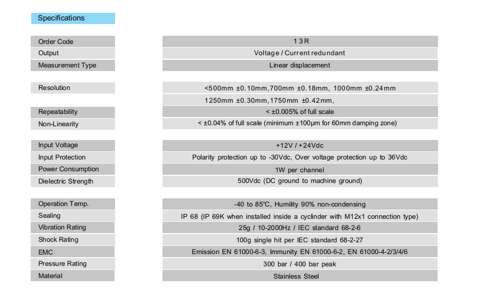
13R redundant output technical specification table
13R dual-channel redundant output specifications: 1 W per independent channel, two independent measuring channels, pressure rating 300 / 400 bar, IP68 / IP69K protection.
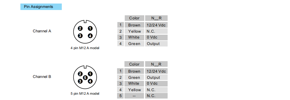
13R dual-channel wiring diagram (Channel A 4-pin / Channel B 5-pin M12)
13R dual-channel redundant wiring diagram: Channel A is a 4-pin M12 A-coded connector, Channel B is a 5-pin M12 A-coded connector, N__R pin assignment.
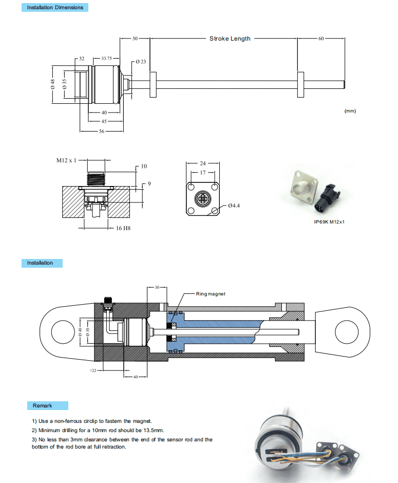
13R installation dimensions and mounting diagram
13R installation dimensions and dual connector photo: Ø48 hex head with dual M12 sockets, precision cast stainless steel housing.
Installation Precautions
- Fix the position magnet with a non-ferromagnetic circlip; ferromagnetic materials will affect measuring accuracy.
- For the 10 mm diameter sensing rod, the minimum bore diameter should be 13.5 mm to ensure adequate installation clearance.
- Keep a clearance of at least 3 mm between the end of the sensing rod and the bottom of the bore to prevent mechanical impact damage to the sensing element.
- Route the two channel outputs to independent acquisition channels to simplify diagnostics, comparison and switchover.
- Both M12 connectors must be tightened and sealed individually to ensure the IP69K protection class.
- Route the signal cable away from high-current lines such as the vehicle battery and starter motor to reduce electromagnetic interference.
Pricing Notes
Because of its two independent measuring channels and redundant design, Series 13R is priced above the standard single-channel 13C model. The price depends on the measuring range, output configuration and connection method. For safety-related applications, please state your functional requirements so we can provide a quotation.


