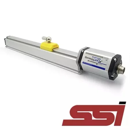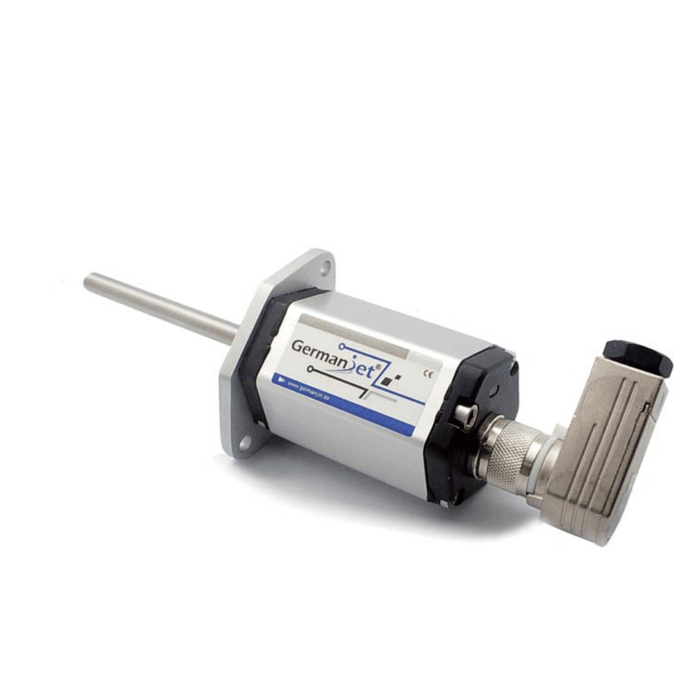
Series 12 General-Purpose Magnetostrictive Displacement Sensor
Compact general-purpose type with analog voltage / Start-Stop output
The Series 12 general-purpose magnetostrictive displacement sensor is a compact position sensing solution designed for wall-thickness control servo cylinders, mounting directly on the cylinder end cap. Its non-contact magnetostrictive measurement delivers high-accuracy, direct absolute position output, eliminating measurement error caused by mechanical wear — no periodic recalibration or maintenance required. Manufactured under ISO 9001 quality management, it works with precision cylinder feedback and closed-loop control systems for high-accuracy position detection. Three interface options are available: analog voltage (0-10 V), current (4-20 mA) and Start-Stop digital. The electronics module is rated IP65 (IP67 with a correctly fitted connector), and the output uses the industry-standard DIN 43650 connector for fast, reliable wiring.
Product Overview
The Series 12 general-purpose magnetostrictive displacement sensor is a compact position sensing solution designed for wall-thickness control servo cylinders, mounting directly on the cylinder end cap. Its small, refined form factor also performs well in hydraulic systems where space is limited.
At its core is non-contact magnetostrictive measurement, delivering high-accuracy, direct absolute position output. The technology eliminates the drift and failure caused by mechanical contact wear in conventional potentiometric sensors, removing the need for periodic recalibration or maintenance and significantly reducing lifetime operating cost.
The electronics module is rated IP65 (IP67 with a correctly connected DIN 43650 connector) and offers excellent vibration resistance (15 g @ 10-2000 Hz), dust protection and humidity resistance, ensuring long-term stable operation in harsh industrial environments.
Operating Principle
The Series 12 works on the non-contact magnetostrictive principle. A high-frequency current pulse travels along the waveguide inside the sensor, generating a circular magnetic field around it. When the external permanent magnet (position magnet) moves along the waveguide with the measured object, the two fields superimpose and cause a magnetostrictive micro-strain in the waveguide material, launching a mechanical strain wave (ultrasonic) that propagates in both directions. The wave travels at a constant sonic velocity (approx. 2800 m/s) and is picked up by the detection coils at both ends of the electronics module, which convert it into a precise time-difference signal. The absolute position of the magnet is then derived from the wave propagation time. The entire measurement involves no mechanical contact, no friction and no wearing parts - delivering genuinely maintenance-free operation and a very long service life.
Typical Applications
Signal Output Types
Analog Voltage Output
120Dual 0-10 V / 10-0 V analog voltage output, suitable for the analog input channels of most PLCs and controllers.
Analog Current Output
1214-20 mA industry-standard analog current output with strong noise immunity, suitable for long-distance transmission and electrically noisy industrial environments.
Technical Specifications
| Measuring Range | 50 ~ 2500 mm |
|---|---|
| Resolution | 120: infinite (controller A/D); 121: 16-bit D/A, 0.0015% (min. 1 μm) |
| Non-Linearity | 120: < ±0.01% FS (min. ±90 μm); 121: < ±0.01% FS (min. ±40 μm) |
| Repeatability | 120: < ±0.005% FS; 121: < ±0.001% FS (min. ±2.5 μm) |
| Update Time | 0.2 ms (Series 12 catalogue) |
| Supply Voltage | DC 24Vdc (20.4 ~ 28.8 Vdc) |
| Output Protection | Reverse polarity protection to -30 Vdc / overvoltage protection to 36 Vdc |
| Insulation Resistance | 500 MΩ (DC ground to machine ground) |
| Operating Temperature | -40°C to +75°C (90% humidity, non-condensing) |
| Protection Class | IP65 / IP67 (with correctly fitted connector) |
| Housing Material | Aluminium, anodised |
| Mounting | M5 × 2 |
| Vibration Resistance | 15g (10~2000Hz) / IEC 68-2-6 |
| Shock Resistance | 100 g (single hit) / IEC 68-2-27 (endurance) |
| EMC Compliance | Emission EN61000-6-3 / immunity EN61000-6-2, EN61000-4-2/3/4/6/8 |
Models and Output Signals
Dimensions and Wiring Diagrams
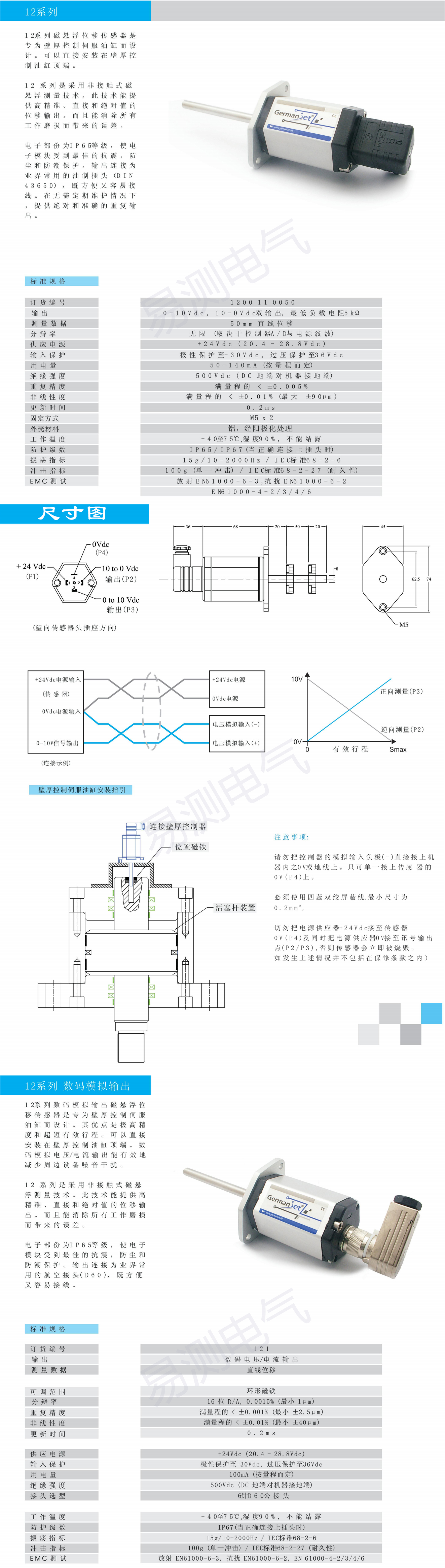
12 Series - Outline Dimensions & Wiring
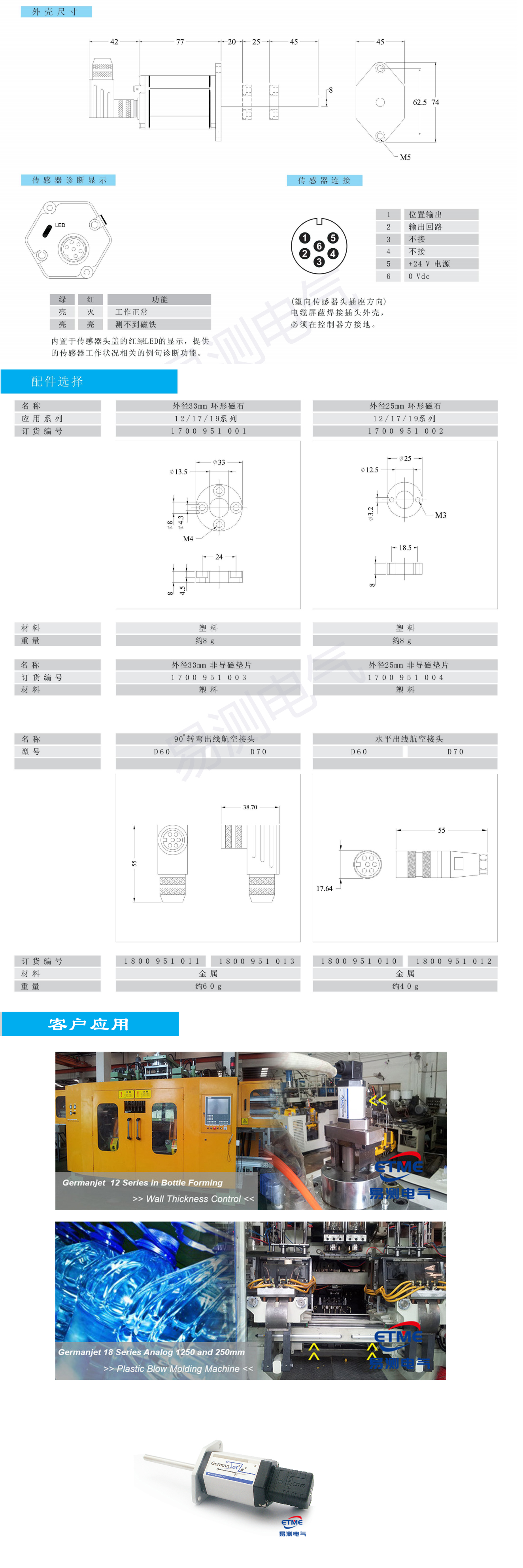
12 Series - Technical Details & Installation
Installation Precautions
- The position magnet must be installed strictly concentric with the waveguide. The clearance between the magnet bore and the sensing rod must meet the installation manual - eccentricity or excessive tightness will cause measurement deviation or even jamming.
- The sensing rod (waveguide) takes axial push/pull loads only. Never subject it to radial force, side bending moment or torsion, and avoid hard interference between the rod and the mounting base.
- Route the signal cable separately from power and variable-frequency drive output cables, keeping them apart. Shielded twisted pair is recommended, with the shield grounded at a single point on the electronics housing.
- Wire strictly according to the DIN 43650 pin assignment. Confirm that the supply voltage (typically 24 VDC) matches the output type to avoid reverse polarity or overvoltage damage.
- Discharge static from your body (touch grounded metal) before handling the electronics module or position magnet, to prevent ESD damage to sensitive components.
- The electronics housing is rated IP65 (IP67 with a correctly sealed DIN 43650 connector) - splash and brief immersion only. Do not direct high-pressure water jets at it or submerge it for extended periods.
- For analog voltage output types, load resistance must not drop below 5 kΩ. For Start-Stop types, confirm the controller counting direction and pulse polarity.
- On first power-up, perform zero and full-scale position calibration to remove zero offset introduced by mechanical installation.
Pricing Notes
Series 12 is a standard general-purpose product. Pricing depends on measuring range (stroke), output signal type (analog voltage / Start-Stop), cable length and order quantity. Share your stroke and output requirements and we will work out an exact quotation for you.



Technical Articles

Mould Height and Nozzle Seat: Two Measuring Points That Are Not Like Injection and Clamping
Read More
A 500 mm Stroke, So Why Order a Longer Range: Working Out Range from Cylinder Stroke
Read More
Discontinued and Out of Stock: Finding a Replacement Magnetostrictive Displacement Sensor
Read More
Measuring Displacement on a Testing Machine: Pairing with Load and Surviving a Million Cycles
Read More
Mechanical, Divider Valve or Servo Closed Loop: Choosing Between Three Ways to Sync Cylinders
Read More