
A 500 mm Stroke, So Why Order a Longer Range: Working Out Range from Cylinder Stroke
When a magnetostrictive displacement sensor is specified, the usual approach is to measure the cylinder stroke, find 500 mm, and tick the 500 mm range on the specification sheet. On commissioning, a short stretch at each end of the travel reads nothing, either alarming or holding the last value.
The reason is straightforward: nominal range is not usable length. There is a structural dead zone at each end of the rod where the return signal cannot be resolved or is absent altogether. That length has to be deducted from the range, and what remains is the usable measuring span.
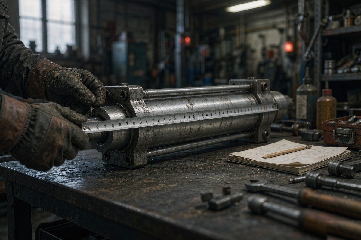
Range and stroke are two different numbers
Stroke is the distance the machine can actually travel, set by the cylinder or by a mechanical stop. It is a physical fact.
Usable range is the length over which the unit produces normal readings. It equals the nominal range minus the dead zones at both ends.
What gets ordered is the nominal range. Of the three, the process cares only about stroke, purchasing orders nominal range, and usable range is the bridge between them. Written out:
nominal range >= stroke + margin at both ends + dead zone at both ends
Ordering range straight from stroke sets both margin and dead zone to zero, and the ends are certain to lose readings.
Three steps from stroke to ordered range
- Measure the real stroke. Not the nominal figure on the drawing, and not an estimate from cylinder length. Measure from mechanical stop to mechanical stop. On older equipment the real stroke and the design value frequently disagree, and it can vary between batches of the same model.
- Leave margin at both ends. Margin exists to absorb assembly tolerance and mechanical deflection — the position the piston actually reaches usually differs from the theoretical limit by a few millimetres. How much depends on machine precision and assembly method: short-stroke, rigid machines need less, long-stroke and high-tonnage machines need more.
- Add the dead zone at both ends. The dead zone is a fixed length set by the structure. The figures differ between series and have to be looked up for the series actually being selected; one experience-based number cannot be applied across a range.
The result of the three steps is a lower bound. Step up to the nearest size in the specification sheet. That is why a 500 mm cylinder frequently ends up with a 560 or 600 mm unit.
Dead zones cannot be estimated
Dead zones exist because of the structure at each end of the rod: one end houses the excitation and pick-up, the other has an end reflection. The length these occupy cannot be recovered, only deducted from the range.
The important point is that the figure differs between series, so estimating from a rough number causes trouble:
| Series type | Dead zone magnitude | Note |
|---|---|---|
| Standard built-in series | Tens of millimetres at each end | The zero zone and the dead zone are separate figures, not one number |
| Series with a different rod end | Over sixty millimetres at one end | Applying a standard figure underestimates it |
| Flexible long-stroke series | Grows with stroke length | The longer the stroke, the larger the front dead zone; no fixed value applies |
For accurate figures for a specific series, consult that series documentation. Measured dead zone values are listed in dead zones at each end of the usable range — match the series, rather than applying one general number across the range.
Four places it goes wrong
Treating range as the length that can be measured. Nominal range is measured from the structural end face, and the usable span sits inside it, inset at both ends. Read the specification note to see which convention is used.
Leaving margin at one end only. Many machines have a hard stop at one end and a hydraulic limit at the other, so the margins needed differ between the two. Work them out separately rather than splitting evenly.
Ignoring travel outside production. During maintenance, die changes and setup, the machine may travel further than it does in production. Confirm these conditions separately, or the reading will be adequate in production and alarm during maintenance.
Assuming all cylinders on a machine have the same stroke. On a multi-cylinder machine the strokes can differ. Size to the longest, and for how ranges are aligned across axes see aligning range and synchronisation.
Three checks before the order goes out
Check the mounting space. Stepping range up makes the rod longer. Bore depth inside the cylinder and available space outside both have to be re-verified against the final range; for built-in types see three things not to get wrong before a built-in hole is drilled.
Check the accuracy class. Once range is increased, resolution and absolute accuracy — both tied to full scale — need re-checking against the process requirement. This runs together with stroke, mounting, environment and output in four steps.
Check the replacement case. On an in-service machine, if the new range differs from the old one, the range scaling in the control program has to change with it. It is not a fit-and-run situation; see three-layer check when replacing a part.
Field notes for engineers
- When measuring stroke, drive the machine to both limits and measure there rather than working from a drawing. Real stroke on older equipment runs both over and under the nominal figure.
- Write stroke, margin and dead zone as three separate numbers on the selection sheet so purchasing orders from them. A single stroke figure on a drawing invites the wrong unit.
- On a multi-cylinder machine, size to the longest stroke, then check that the shorter-stroke cylinders still operate in the middle of their usable range, where linearity is normally best.
- If a unit with too little range is already fitted, the ends will read nothing. Parameter changes cannot create physical length — only a longer specification or a better mounting position will fix it.
- If the specification changes after the order is placed, make sure the final range reaches the control and process teams, or the machine will arrive with the old scaling still in the program.
Frequently Asked Questions
Q: Why can the range not simply be set to the stroke?
Because nominal range is not usable length. Each end of the rod has a structural dead zone where no reading is produced, and that length has to be deducted from the range. Ordering to stroke sets both margin and dead zone to zero, so both ends lose readings. The correct lower bound is stroke plus margin plus dead zone.
Q: What value should be assumed for the dead zone?
There is no general value. The dead zone is set by the structure at the end of the rod and differs between series — one series has over sixty millimetres at one end, and flexible long-stroke versions have a front dead zone that grows with stroke. Look the figure up for the series being selected; applying another model value will underestimate it.
Q: How much margin is appropriate?
It depends on assembly tolerance and machine rigidity, and there is no fixed figure. Short-stroke, rigid machines need less; long-stroke and high-tonnage machines need more. Work out the two ends separately, because many machines have a hard stop at one end and a hydraulic limit at the other, and the margins required are not equal.
Q: Does stepping the range up one size hurt accuracy?
It affects the figures tied to full scale, mainly resolution and absolute accuracy, because both are referred to full range. After stepping up, re-check those two against the process requirement. Undersizing is worse in a more direct way: the magnet enters the dead zone and the reading is lost entirely, which is a usability problem rather than an accuracy one.
Related Products

Series 12 General-Purpose
View Product
Series 16 Hydraulic Cylinder Built-in
View Product
Series 17 Hydraulic Cylinder Integrated
View Product
Series 19F Flexible Long-stroke
View ProductRelated Applications

Multi-Industry Application Cases for Magnetostrictive Displacement Sensors
View Details
Series 16 Hydraulic Rod Magnetostrictive Displacement Sensor Application Cases
View Details
Series 19H Cylinder-Integrated Process Displacement Sensor Application Cases
View Details