Magnetostrictive Displacement Sensors in the Field
21 clips shot on site — real installations and applications on injection molding machines, presses, storage tanks and test benches.
Everything here was shot on site, with no animation standing in for the real thing. You can see exactly where the sensor sits on an injection molding machine, a press, a storage tank or a test bench, how the cabling is routed, and how the position value finally appears on the controller. Long strokes, heavy machine vibration and expensive downtime are what these measurement points have in common — seeing how a gauge is actually mounted usually tells you more than a datasheet.
Injection Molding8 clips
Clamp, moving platen, ejector and injection positions on an injection molding machine all depend on stroke feedback. The footage below comes from two-platen machines, a blow molding machine and a mold automation unit, showing where the gauge is mounted, how cabling is routed, and how the position value ends up on the controller and HMI.
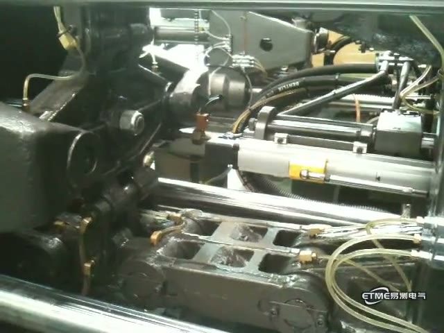
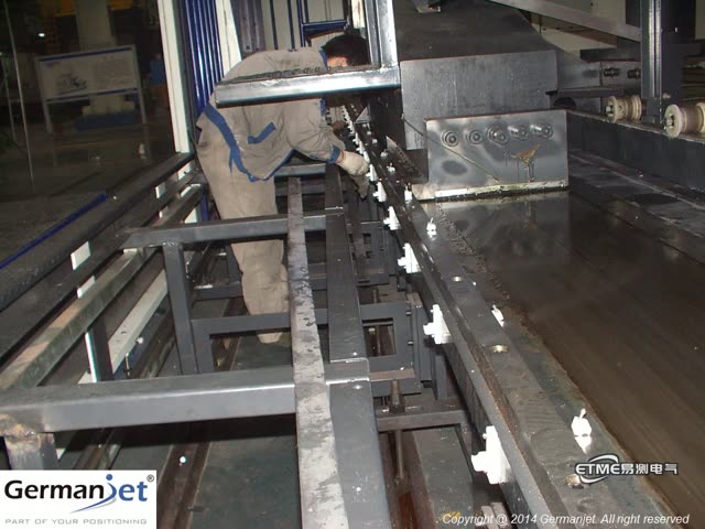
Large Two-Platen Machine — Gauge Mounted Along the Guide Rail
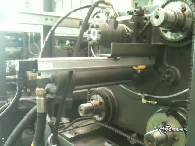
A continuous look at the clamp area of a large two-platen injection molding machine. The gauge runs along one side of the machine guide rail, with the body, slider and terminal wiring all in frame — showing how much space the sensor takes up, how it is fixed and how the cable is routed. Two-platen machines mean long strokes and heavy loads, so mounting parallelism and vibration resistance matter most.
0:47
Two-Platen Machine — Tie-Bar Position and Control Cabinet
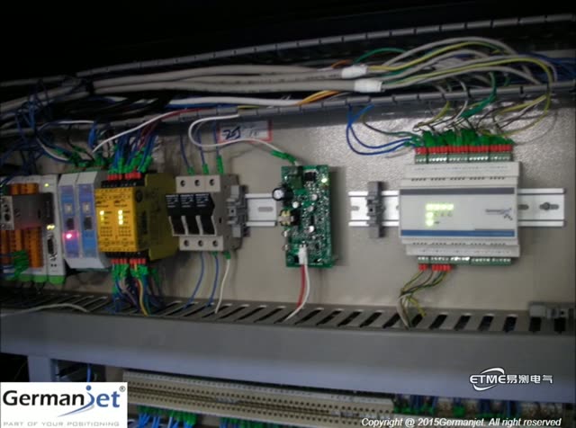
The focus here is the control cabinet: the interface unit that brings gauge signals onto EtherCAT, Ethernet and USB, with corresponding channels labelled on the module. The accompanying HMI shows all four tie-bar positions (around 29.80 mm) alongside mold data — the gauges are part of the machine control system, not standalone instruments.
0:56
Multiple Digital Gauges — Mounting and Seal Fitting
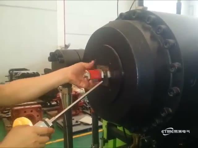
Mounting of digital gauges on a two-platen machine: how the gauge sits at the clamp cylinder flange, how the seal ring is fitted and tightened, with an on-screen note on seal selection. Whether the seal is done properly decides the long-term stability of a long-stroke measuring point in an oily environment.
1:18
Large-Tonnage Clamp Unit — Tie Bars and Moving Platen
Multi-angle footage of the clamp section on a large injection molding machine: tie bars, the moving platen and the clamp mechanism through an open-close cycle. Long-stroke clamp position is a critical measurement point here, with the gauge sitting between the platens under continuous vibration and off-center load.
0:13
Mold Close Motion — Profile Gauge Mounting
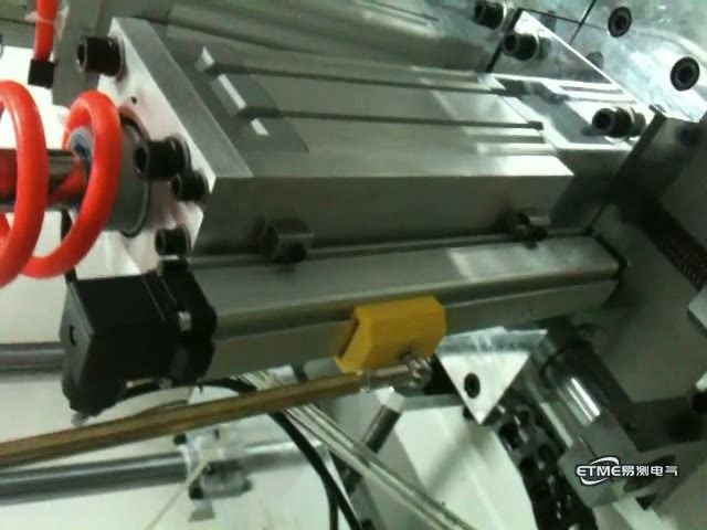
Fixed-camera footage of the mold closing motion, with a clear view of how the profile gauge is mounted: the aluminum profile body fixed to the frame, the read head traveling with the moving platen, piping taken off through brass fittings. Useful as a mounting reference when sizing a gauge.
0:18
Ejector Mechanism — Position Feedback Installation
Footage of the ejector drive area, with the gauge routed alongside the hydraulic lines to measure ejector stroke. Ejector motion is frequent and fast, which puts both response speed and vibration resistance to the test.
0:37
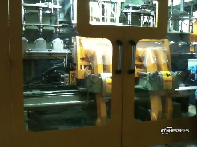
Blow Molding Machine — Mold Carriage Movement
Interior motion of a blow molding machine filmed through the viewing window, showing the mold carriage moving back and forth. Blow molding needs consistent, repeatable mold positions — position drift shows up directly in part consistency.
2:30
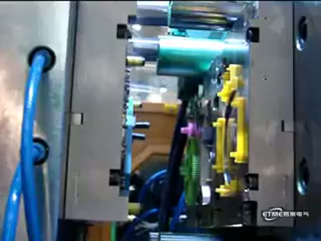
Mold Automation Unit — Position Measurement Points
A continuous walkthrough of a mold automation unit, covering measurement points on the mold frame, cable carriers and auxiliary equipment. Source footage is early low-resolution material shot on site.
Presses & Heavy Equipment4 clips
Press main cylinders need absolute feedback so that every pressing stroke lands the same. This section covers the full slider stroke on a vertical press, the sensor mounting point on a hydraulic cylinder, and multi-cylinder coordination on a six-axis platform.
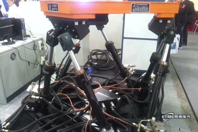
A six-degree-of-freedom motion platform at a trade show, its deck carried by multiple electro-hydraulic servo cylinders. Coordinated motion on a platform like this is impossible without absolute position feedback on every cylinder — a textbook multi-cylinder synchronization application.
0:38
Vertical Press Slider Stroke — Shot in Portrait
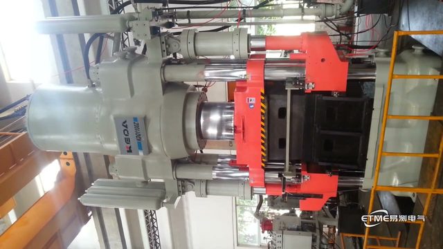
The full up-and-down slider stroke on a vertical press, shot in portrait. The vertical framing captures the complete travel range, making the main cylinder stroke and the position feedback point easy to read.
0:19
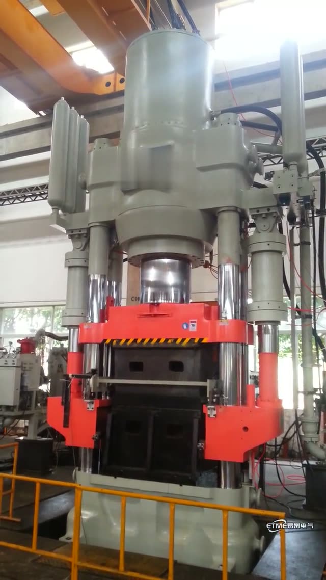
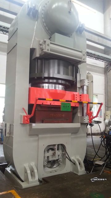
Vertical Press — Frame and Main Cylinder
An overview of a vertical press showing the upper beam, main cylinder and frame columns. This class of machine usually needs absolute position feedback on the main cylinder to keep pressing strokes consistent.
0:21
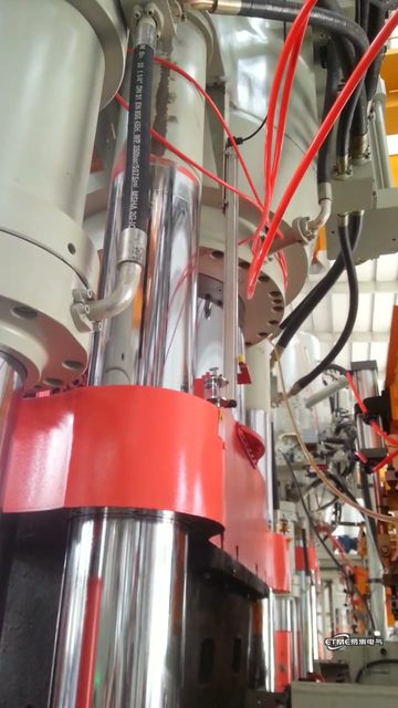
Press Hydraulic Cylinder — Sensor Mounting Point
Close-up of a press hydraulic cylinder area, with the sensor mounted on the cylinder body and sheathed cable routed along the frame. Whether a gauge is mounted inside or outside the cylinder directly affects how easy maintenance will be later.
Level Sensing3 clips
On large storage tanks, the hard part of level measurement is rarely the sensor itself — it is uncoiling the flex gauge, getting it onto the tank roof and fixing it at the flange. Three clips below record that installation sequence from start to finish.
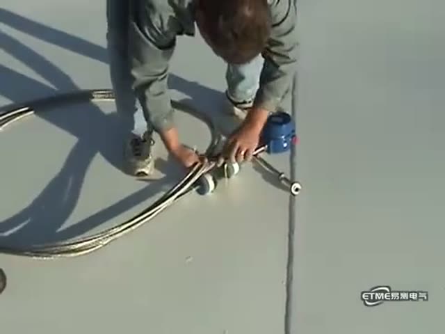
Flexible Level Gauge — Uncoiling and Straightening
A flexible level gauge uncoiled from its shipping reel. Flex gauges serve large storage tanks: coiled for transport and uncoiled on site, where the straightening and fixing method determines the measurement zero point.
1:02
Flexible Level Gauge — Carrying It to the Tank
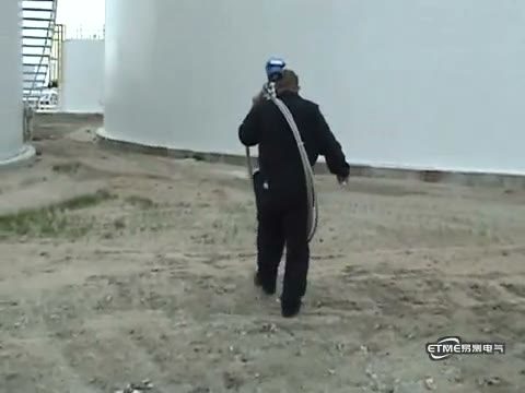
Installers carry the coiled flex gauge through the tank farm and up the tank's side ladder to the roof. Getting the gauge up and securing it is the awkward part of level measurement on large tanks, and this footage captures the whole process.
0:26
Tank Roof — Level Gauge Flange Installation
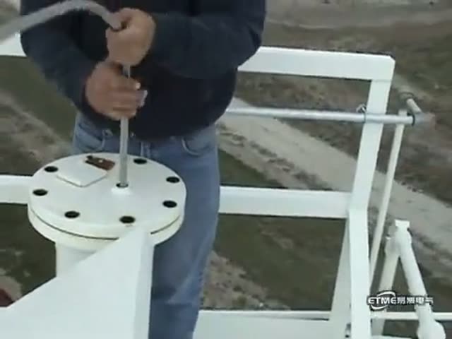
Installation detail at the tank roof flange: the gauge probe goes down through the center port and the junction box is fixed on top, with the camera on the sealing face and the tightening technique. Flange sealing and verticality set the foundation for level measurement accuracy.
Principle & Testing5 clips
Two questions come up before every selection: what exactly is a magnetostrictive gauge measuring, and just how stable is an analog output? The clips here answer both directly — a transparent cylinder, a host software readout, and bench test rigs.
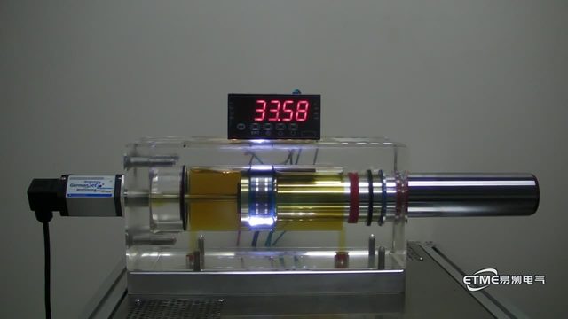
A principle demo built around a transparent acrylic cylinder. Inside, the yellow magnet moves along the probe while the digital display tracks it — six readings matching different magnet positions. When words fail to explain how magnetostriction works, this shows at a glance what is being measured and why nothing touches.
0:32
CANbus Digital Output — Reading Position Directly
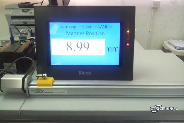
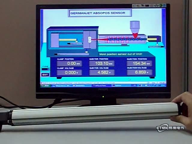
A profile gauge wired to a touch panel that reads out magnet position in mm, updating in real time as the magnet is pushed by hand. This is a digital (bus) gauge: position travels as a digital value on the bus, so the controller needs no further A/D conversion or on-site calibration.
0:57
Setup Software — Live Position and Speed Readout
Software bring-up on a bench setup. The host software shows current position, previous position and travel speed together, with values following the magnet in real time — used to check that the gauge and the acquisition side agree.
1:31
Analog Output Verification — mV Stability on a 6.5-Digit Meter
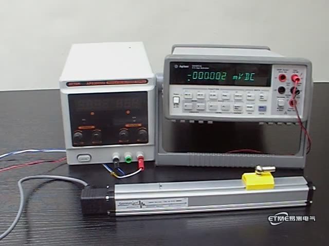
Analog output verification on a bench: the gauge is powered from a DC supply with its output wired to a 6.5-digit multimeter, reading mV-level changes as the magnet is pushed by hand. This answers the question engineers ask most — how stable is an analog gauge, and how many digits can you trust? Same verification method as our Lijin 3500-ton troubleshooting record.
0:27
Vibration Bench — Resistance Testing
A gauge under test on a vibration bench, elastic elements and fixtures working under continuous vibration. Machine vibration is one of the most common causes of displacement sensor failure on site, and bench testing like this verifies output stability under sustained vibration.
Operation & Maintenance1 clips
Installation, calibration and servicing filmed as they happen, on the shop floor and on the bench with no animation standing in — usable directly as a reference for maintenance staff.
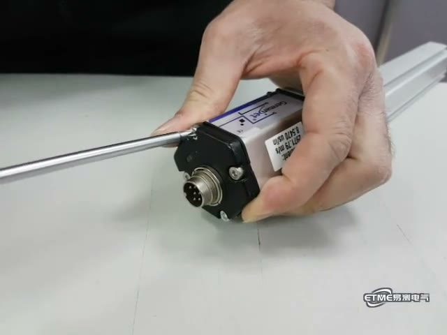
A complete service tutorial for the 19 series (IP67) gauge: removing the cap screws, lifting the cap to expose the internal board and terminal block, unplugging and reseating connectors, then refitting the screws. Filmed end to end without cutting steps, it works as a reference for maintenance staff — and the internal wiring is visible, which is the direct evidence of how serviceable the design really is.
All 21 clips are recorded on site, taken from projects we have delivered. Need the mounting arrangement for a specific machine or measurement point? contact us and we can pull the matching footage for your application.
Keep Exploring
Recommended Sections
The clips show how the job is done on site. Specs, delivered projects and selection notes live in these sections.
Standard models are typically 3 to 4 weeks. Where the stroke, output type or interface is a special requirement, the lead time is confirmed against the production schedule when the order is placed. If a project or a maintenance window has a fixed date, tell us up front and we will answer against the actual schedule.
Are any models held in stock?
A small number of specifications are kept in stock and the rest are built to order. Stock varies with the model and the current inventory, so confirming the exact model with us before ordering is the reliable route; models in stock can be shipped straight away.
What warranty do you offer?
The warranty is one year. If a quality problem appears within that period, contact us and the case goes through our after-sales process.
Can you supply custom, non-standard versions?
Yes. Drawing on the full 12 / 13 / 16 / 17 / 18 / 19 series, the measuring range, interface, mounting method and protection class can be adapted to the application. Send us the working conditions and the parameters you need, and we will come back with what can be done.

 0:40
0:40