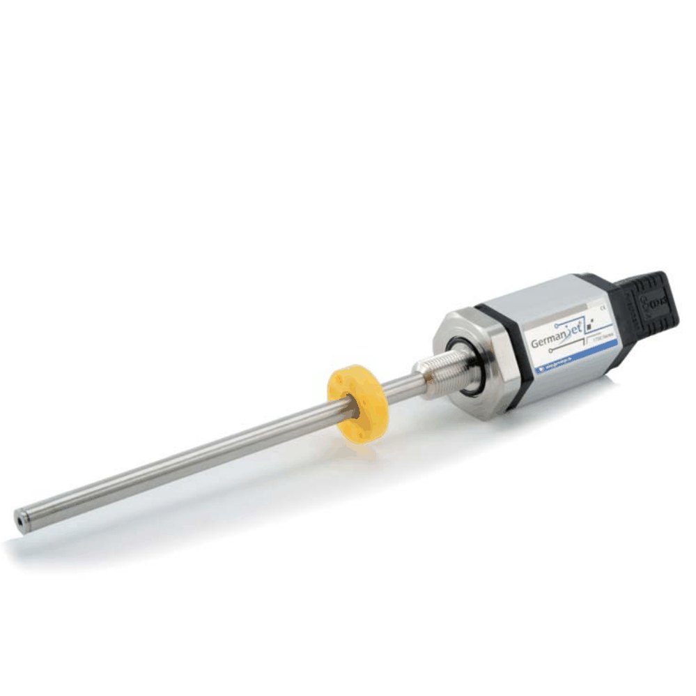
Series 17 hydraulic cylinder integrated magnetostrictive displacement sensor
Integrated into hydraulic cylinder, modular electronics, DIN 43650 connector
Series 17 is Germanjet's flagship product line, engineered for integration into hydraulic cylinders. Its pressure tube and hex flange are made of 100% stainless steel, allowing direct installation inside the cylinder. The original modular assembly design means the electronics housing and pressure tube are fully separable: in special cases only the electronics need to be removed for calibration, without separating the pressure tube from the cylinder - cutting maintenance downtime dramatically and raising productivity. A wide range of signal interfaces is available: analog voltage (0-10 V / 10-0 V), analog current (0-20 mA, 20-0 mA, 4-20 mA, 20-4 mA) and Start-Stop digital. IP65/IP67 protection, DIN 43650 standard connector (or D56 aviation plug / M12 / flying lead), M18x1.5 flange thread mounting, measuring stroke selectable from 100 mm to 4000 mm. Models 170-175.
Product Overview
Series 17 is Germanjet's flagship product line, designed for deep integration into hydraulic cylinders. The pressure-resistant outer tube and hex flange are precision cast from 100% stainless steel and can be installed directly inside the hydraulic cylinder, withstanding operating pressures of up to 350 bar (600 bar peak).
The original modular assembly design is the core competitive advantage of Series 17: the electronics housing and the pressure tube are two completely independent modules that can be separated at any time. For on-site calibration, parameter adjustment or troubleshooting, the engineer only needs to remove the electronics, without separating the pressure tube from the hydraulic cylinder. This design cuts the maintenance downtime of conventional cylinder sensors from several hours to minutes, significantly improving overall production line efficiency.
A wide range of signal interfaces is available: analog voltage (0-10 V / 10-0 V), analog current (0-20 mA, 20-0 mA, 4-20 mA, 20-4 mA) and Start-Stop digital pulse. Whether your control system is a conventional PLC or the latest Industry 4.0 smart platform, Series 17 integrates seamlessly. The electronics module is rated IP65/IP67, with output interfaces compatible with the DIN 43650 standard connector, D56 6-pin aviation plug, M12 5-pin circular connector and flying lead cable.
Operating Principle
Series 17 uses the non-contact magnetostrictive measurement principle; its distinguishing feature is the modular mechanical + electronic architecture. The waveguide is sealed inside a 100% stainless steel pressure tube that withstands up to 350 bar inside the cylinder (600 bar peak). The electronics housing is a separate module fixed outside the cylinder by a hex flange, connected through a sealed electrical interface. During measurement, the permanent magnet (position magnet) mounted on the piston moves with the piston, triggering the magnetostrictive effect in the waveguide; the strain wave travels to the electronics housing where it is detected and decoded. The benefit of the modular design: for on-site calibration or troubleshooting only the electronics housing is removed, leaving the pressure tube and cylinder untouched - cutting downtime from hours to minutes.
Typical Applications
Signal Output Types
Voltage output 0-10 V
170Dual 0-10 V / 10-0 V analog voltage output, compatible with the analog input channels of most PLCs and motion controllers.
Current output 0-20 mA
1710-20 mA analog current output with high noise immunity, suitable for long-distance transmission and industrial noise environments.
Current output 20-0 mA
17220-0 mA reverse analog current output for control systems requiring an inverted signal.
Start-Stop digital type
173Start/Stop pulse digital signal output for applications requiring precise switching point detection; no A/D conversion required.
Current output 4-20 mA
1744-20 mA industry standard analog current output with high noise immunity, suitable for long-distance transmission and industrial noise environments.
Current output 20-4 mA
17520-4 mA reverse analog current output for control systems requiring an inverted signal.
Technical Specifications
| Measuring Range | 100 ~ 4000 mm (analogue catalogue; update-time table to 7600 mm) |
|---|---|
| Resolution | Analogue: infinite (controller A/D); Start/Stop: 0.01 / 0.005 mm |
| Non-Linearity | < ±0.02% FS (min. ±90 μm) |
| Repeatability | < ±0.001% FS |
| Update Time | 0.5 ms (≤1200 mm) / 1.0 ms (≤2500 mm) / 2.0 ms (≤4800 mm) / 5.0 ms (≤7600 mm) |
| Supply Voltage | DC 24Vdc (20.4 ~ 28.8 Vdc) |
| Output Protection | Polarity protection to -30 Vdc / overvoltage protection to 36 Vdc |
| Insulation Resistance | 500 MΩ (DC ground to machine ground) |
| Pressure Rating | 350 bar working / 600 bar peak (in-cylinder) |
| Operating Temperature | -40 °C to +75 °C (90% humidity, non-condensing) |
| Protection Class | IP65 / IP67 (when the connector is properly mated) |
| Connector | DIN 43650 / D56 6-pin aviation connector / M12 5-pin / direct cable outlet |
| Mounting | M18 × 1.5 flange thread |
| Piston-rod bore | ≥12.7 mm; cap through-hole Ø13 mm, mounting face ≥Ø35 mm |
| Housing Material | Aluminium (anodised) + stainless steel (pressure tube / flange) |
| EMC Compliance | Emission EN61000-6-3 / Immunity EN61000-6-2, EN61000-4-2/3/4/6/8 |
Models and Output Signals
Dimensions and Wiring Diagrams
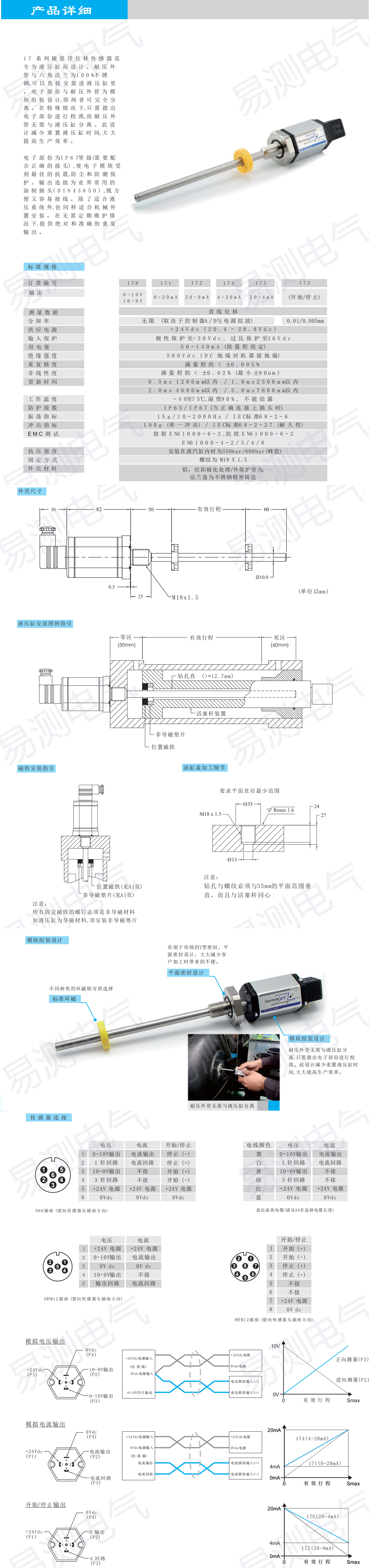
17 Series - Outline Dimensions & Cross-section
17 Series - Mounting & Connector Pinout
Installation Precautions
- Series 17 is integrated directly into the hydraulic cylinder. Before installation confirm that the cylinder cap interface matches the sensor hex flange.
- The hex flange is a modular design. Use the correct spanner when removing the electronics housing to avoid damaging the sealing face.
- Power and output are connected via the DIN 43650 connector. Wire strictly according to the pin assignment and tighten securely to achieve the rated protection class.
- For analog output, keep the signal ground separate from the power ground. Ground the shield at one end only to avoid ground loops.
- The rod is a pressure-resistant outer tube that carries axial load only. The magnet ring moves with the piston rod and must remain concentric.
- The 100% stainless steel outer tube is suitable for hydraulic oil, but prolonged contact with incompatible media must be avoided.
- Piston-rod bore ≥12.7 mm (Ø10 rod); cylinder cap M18×1.5, through-hole Ø13 mm. 350 bar working / 600 bar peak. Magnet screws must be non-magnetic; add a non-magnetic washer on a magnetic cylinder body.
- Catalogue ring magnets: 1700 951 001 (Ø33 mm) and 1700 951 003 (Ø25 mm). Magnet screws must be non-magnetic.
Pricing Notes
Series 17 offers a full model range (170-175, covering analog voltage, analog current and Start-Stop). Pricing depends on measuring range, output interface (0-10 V voltage / 0-20 mA, 20-0 mA, 4-20 mA, 20-4 mA current / Start-Stop) and mechanical specification.



Technical Articles
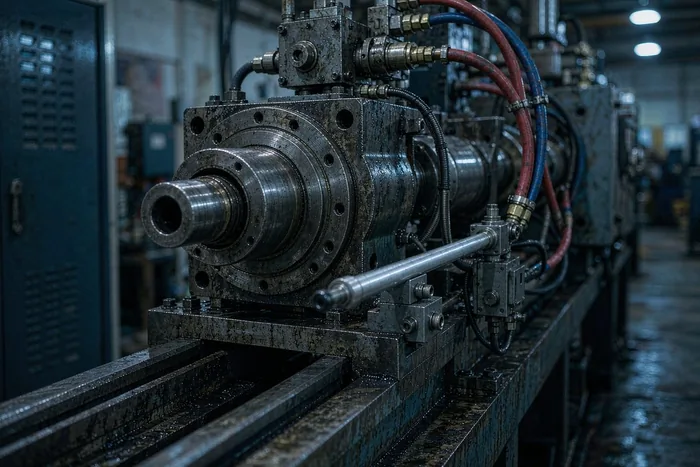
How to Set the Injection to Packing Switchover: Time, Pressure or Position
Read More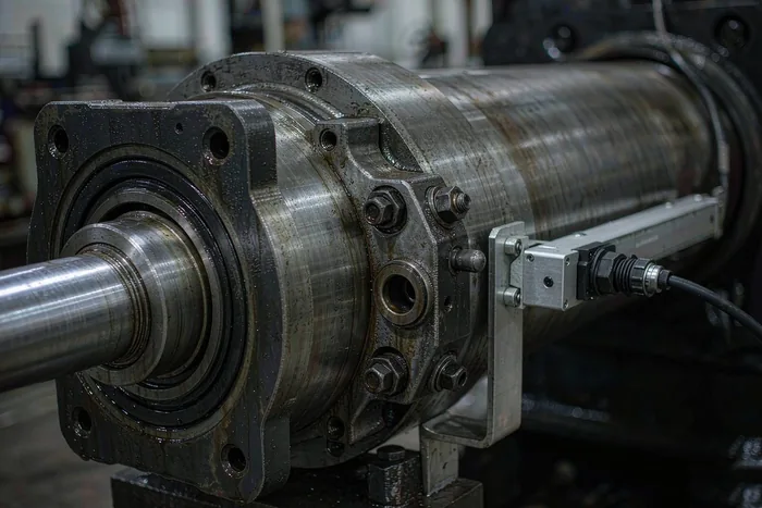
The Last Few Centimetres: How Cushioning Changes the Reading, and How to Read the Cushion
Read More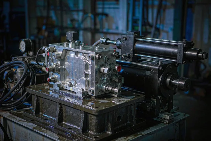
Two Feedback Loops, Not One: Why Spool Position and Cylinder Position Are Measured Separately
Read More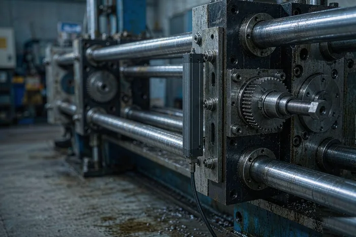
Mould Height and Nozzle Seat: Two Measuring Points That Are Not Like Injection and Clamping
Read More
Where to Mount a Magnetostrictive Displacement Sensor: The Wrong Position Moves Both Stroke and Accuracy
Read More
Replacing a Magnetostrictive Displacement Sensor in a Hydraulic Cylinder: Record Before You Remove
Read MoreRelated Applications

Multi-Industry Application Cases for Magnetostrictive Displacement Sensors
View Details
Series 17 Hydraulic Cylinder Integrated Magnetostrictive Displacement Sensor Application Cases
View Details