
Mould Height and Nozzle Seat: Two Measuring Points That Are Not Like Injection and Clamping
Specifying measuring points on an injection moulding machine usually runs along a familiar path: injection, clamping and ejection are specified, and the job is considered done. Whether the mould height and nozzle seat points need anything at all is often settled by copying the machine next door.
Those two points are genuinely different in kind. Mould height is a dimension, and the nozzle seat only moves between two ends — neither is a case of how far the workpiece travelled. Once it is clear what they actually measure, whether to fit anything and what to fit answers itself.
How Many Measuring Points Does a Machine Have
A standard machine normally carries three: injection (screw position), clamping (opening stroke) and ejection (ejector stroke). Machines with full closed loop control or a high level of automation add two more: mould height and nozzle seat.
The first three are already broken down by station in how many sensors one machine needs — injection demands most, clamping next, ejection one grade looser. The two that get glossed over are the last pair.
They get glossed over because their values can be obtained without adding a measuring point at all, and to an accuracy the process accepts. Whether to upgrade depends on the machine and how it is used, not on a general rule.
Mould Height: A Dimension, Not a Travel
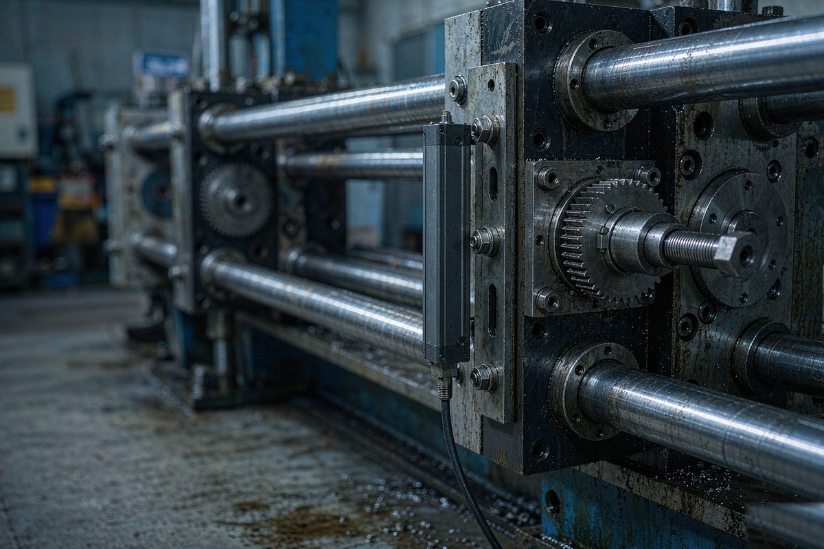
The mould height mechanism changes the distance between moving and fixed platen so that moulds of different thickness close correctly. Drive is usually a mould height motor turning a gear set or an adjusting nut.
Two values are involved, and they are quite different in nature:
- Mould height — the actual distance between the two platens. This is a dimension, and what matters is accuracy and repeatability, not speed.
- Adjustment complete — a status value, needing only a clear arrived and not arrived.
The first sets process parameters and the clamping force window; the second is a safety interlock. Traditionally the height figure is derived from turn counting and the status from a proximity switch. Neither needs millisecond response.
Nozzle Seat: The Loosest Point on the Machine
The nozzle seat carries the whole barrel forward and back, advancing to seat the nozzle against the mould sprue and retracting for purging and material changes.
On most machines only two positions matter: seated and retracted. The travel between them needs no continuous monitoring, which is why the traditional arrangement is two limit switches with the stroke rarely even displayed.
On accuracy, injection is often specified to micrometre grade while the nozzle seat is content with millimetre grade. It governs the reliability of nozzle contact and takes no part in metering calculations. That gap is the starting point for deciding whether it deserves anything sophisticated.
Why These Two Are Normally Left Out
Three reasons combine to make designers skip them by default.
The values are not continuous. Arrival is a switch state, and measuring a switch state with a continuous output unit is capability in excess of need.
Space and cost. The mould height side is already crowded with the gear set and clamping structure, so adding a rod means finding a mounting face and a cable route; the nozzle seat stroke is short, which limits the forms available.
The old methods work. Height by counting, arrival by limit switch — both cheap, both decades old, both unlikely to fail.
The conclusion is not that these points should be fitted, but that leaving them out is reasonable by default. The real question is whether the way the machine is used has outgrown the old methods.
Three Cases That Justify a Measuring Point
- Frequent mould changes with automatic set up expected. Manual adjustment relies on a person and a few trial closures; automatic adjustment needs the current mould height and the distance the mechanism has moved, so that one calculation lands correctly. The height then has to be a live readable value rather than a figure derived from counting.
- Mould protection is critical, or process records are required. Thin wall and precision moulds have a narrow clamping force window, and a height error of a fraction of a millimetre can mark the face. Where height and nozzle seat position must be written into the process recipe and archived per batch, discrete switch signals no longer suffice.
- Older machines being re-controlled, with counting or limits already unreliable. Counters and proximity switches wear and start skipping. If the replacement controller already accepts analogue or bus inputs, one position channel is less work than repairing a counter, along the same lines as adding detection without disturbing the cylinder.
How Much Looser the Selection Can Be
| Station | What it measures | Accuracy grade | Usual form |
|---|---|---|---|
| Injection (screw) | Screw travel, feeds metering | Micrometre repeatability | Magnetostrictive displacement sensor, short stroke, fast response |
| Clamping (stroke) | Platen travel | Tenths to hundredths of a millimetre | Magnetostrictive displacement sensor, flat housing to save radial space |
| Ejection (stroke) | Ejector travel | Tenths of a millimetre | Compact short range unit |
| Mould height | Platen to platen distance | Tenths of a millimetre is enough | A unit, or derived from counting |
| Nozzle seat | Advance and retract | Millimetre grade is enough | Limit switches, a unit where justified |
Laid out in a row, the picture is clear: for mould height and nozzle seat the selection can be relaxed a long way from the injection grade. Repeatability of a tenth of a millimetre, or even a millimetre, is sufficient, and high refresh rates are unnecessary — mould height adjustment is slow by nature and the nozzle seat needs no continuous tracking.
What is saved can be spent elsewhere: a higher ingress protection rating for the shop floor, generous margin on range for the mechanism actual travel, and a mounting form that fits the space available. The logic here is sufficient and fits, not the highest specification available. The full parameter conventions across stations are compared in clamping force and shot size closed loop.
Once these points feed a loop, the split between inner and outer feedback comes into play, as set out in two feedback loops in a servo valve circuit.
Two Mistakes Most Often Made When Fitting Them
- Measuring the adjusting screw and calling it mould height. How far the screw turned is not the distance between platens — backlash in the gear set and wear in the nut both show up as a difference. To measure height, the feedback point belongs on the moving platen or on a part rigidly connected to it, the same principle as mounting position defines the datum.
- Copying the injection specification onto the nozzle seat. The seat stroke is short and accuracy demands are low, so importing the injection grade costs money that buys nothing and leaves a long rod to fix in a cramped space. Each station should be specified against its own travel and space.
Field notes for engineers
- Before upgrading mould height measurement, count how often the machine changes mould in a month. At low frequency the benefit of a live height value rarely covers the work involved.
- For the mould height point, measure the platen to platen distance with a calliper during assembly and store that figure as the calibration datum in the controller. It can then be reproduced at any time without stripping the mechanism.
- On short stroke stations such as the nozzle seat, fix the rod on the stationary side and carry the magnet on the moving part. Reversing this puts the cable through a full return cycle every stroke and shortens its life noticeably.
- Vibration damping mounts apply here as well, particularly to the contact shock as the seat advances. The installation figures are set out in the anti vibration clamp fitting guide.
Frequently Asked Questions
Q: How many position measuring points does an injection moulding machine have?
A standard machine normally has three: injection, clamping and ejection. Mould height and nozzle seat are extension points, added on machines with full closed loop control or high automation. On most machines mould height is derived from turn counting and the nozzle seat is handled by limit switches, both adequate for the process.
Q: For the mould height point, should height or adjustment travel be measured?
They are different quantities. Mould height is the actual distance between platens, a dimension used to set process parameters and the clamping force window; adjustment travel is how far the mechanism moved, used to confirm completion. Measuring at the adjusting screw gives travel, not height — gear backlash and nut wear separate the two.
Q: What accuracy grade do mould height and nozzle seat need?
A grade below injection is enough. Mould height at a tenth of a millimetre satisfies height setting and mould protection, and the nozzle seat at millimetre grade confirms reliable nozzle contact. Neither takes part in metering calculations and neither needs a high refresh rate, so the selection range is much wider than for injection.
Q: When do these two points justify a magnetostrictive displacement sensor?
Three situations: automatic mould setting with frequent changes; a narrow mould protection window or a requirement to log height into the process record; and older machines where counters and limit switches are no longer reliable. In each case a discrete signal or a derived figure stops being enough, and a continuously readable position becomes worthwhile.
Related Products

Series 16 Hydraulic Cylinder Built-in
View Product
Series 17 Hydraulic Cylinder Integrated
View Product
Series 19 H-Type Built-in Cylinder
View Product
Series 12 General-Purpose
View ProductRelated Applications
Ejector Sensor Jitter on an Injection Moulding Machine: From Mounting Plate Resonance to the Standard Clip Fitting
View Details
Series 16 Hydraulic Rod Magnetostrictive Displacement Sensor Application Cases
View Details