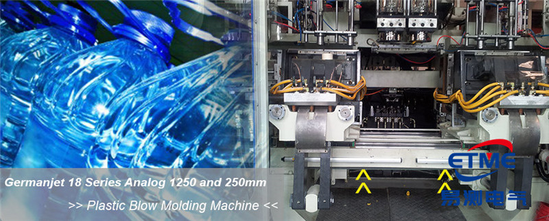
Injection Moulding Machine Displacement Sensor: Three Ruler Positions and Wiring
An injection moulding machine measures position in three places: the clamp, the ejector and the injection unit. This article shows where the displacement sensors (electronic rulers) go, when to choose magnetostrictive over a potentiometer ruler, the wiring points, and the steps from fitting to production.
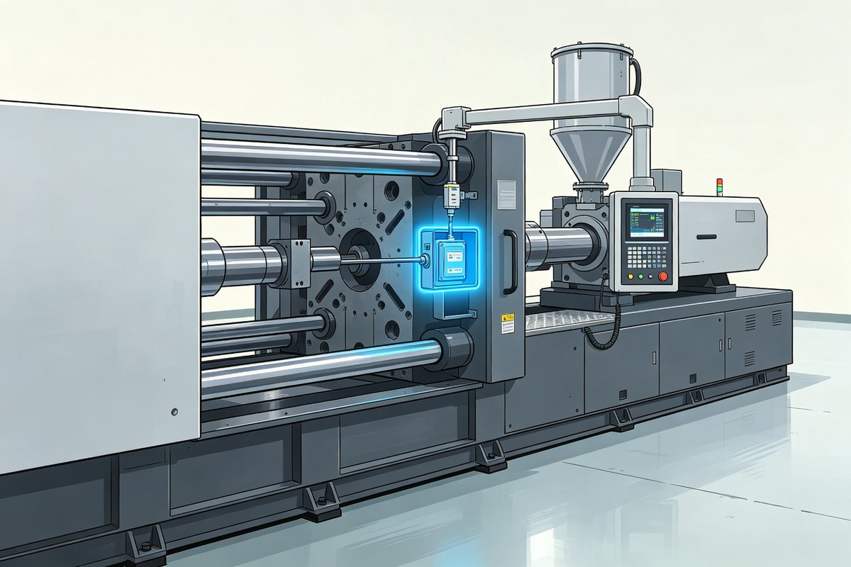
Where the sensors go
- Clamp unit — clamp / unclamp stroke and mould height; the largest travel on the machine.
- Ejector unit — ejector stroke; shorter but cycled constantly.
- Injection unit — screw and injection travel; accuracy here decides shot consistency.
Magnetostrictive or ordinary electronic ruler?
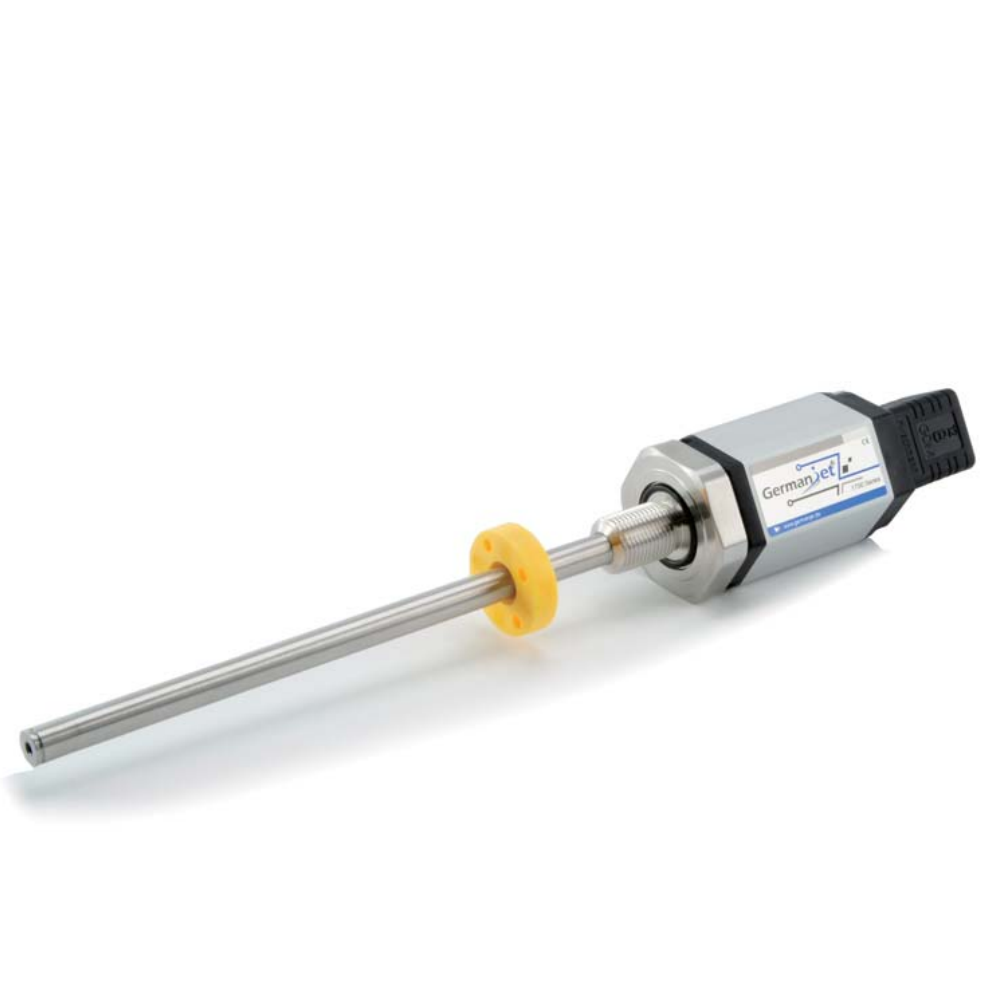
A potentiometer (conductive plastic) ruler is cheap and fine for dry, low-cycle positions. Choose magnetostrictive when the axis is fast, continuous, oily or precision-critical — clamp position on a big machine, injection travel on a precision moulding machine. Magnetostrictive is non-contact, so there is no wiper to wear out on a machine that cycles all day.
Wiring points
- Analogue (4-20 mA / 0-10 V): four-wire — supply pair and signal pair independent.
- Bus (CANopen / Profibus): follow the digital pin table, termination at both ends. SSI and CANopen versions take their node address and baud rate from the configuration software.
- Route cables away from the heating bands and the moving platens.
Steps from fitting to production
- Select the stroke with margin and mount the sensor parallel to the travel.
- Fit the magnet ring so it never leaves the calibrated range.
- Wire, power up, and slide the axis by hand — the reading must move smoothly.
- Set zero at the reference position and span at the far position.
- Run one dry cycle and check the values the PLC sees at each phase.
Four things to watch
- The ring must never hit the mechanical ends — hard stops bend it.
- Leave cable slack for the moving axis; a tight cable breaks inside the boot.
- Keep the sensor away from the heating bands; add a heat shield if needed.
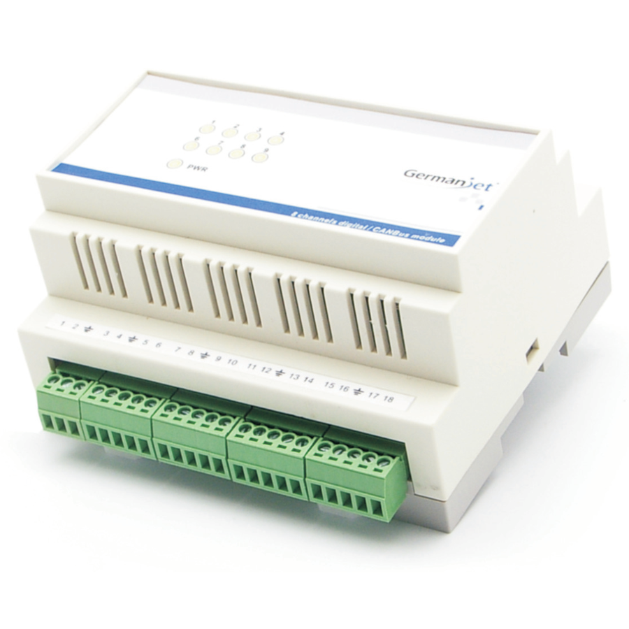
- Many rulers on one machine: use a CANbus integration module to keep the node count low. A moulding machine typically carries seven rulers and one CANbus card handles two at most; the integration module collects all seven into one node, and the PLC scans them seven times faster.
Wiring tables for the digital series are in the complete wiring reference.
Frequently Asked Questions
Q: Where do the sensors go on an injection moulding machine?
Three places: the clamp unit (clamp stroke and mould height), the ejector unit (ejector stroke) and the injection unit (screw and injection travel).
Q: When is magnetostrictive worth it here?
When the axis is fast, continuous, oily or precision-critical — clamp position on a big machine and injection travel on a precision machine. Otherwise a potentiometer ruler is economical.
Related Products
Related Applications
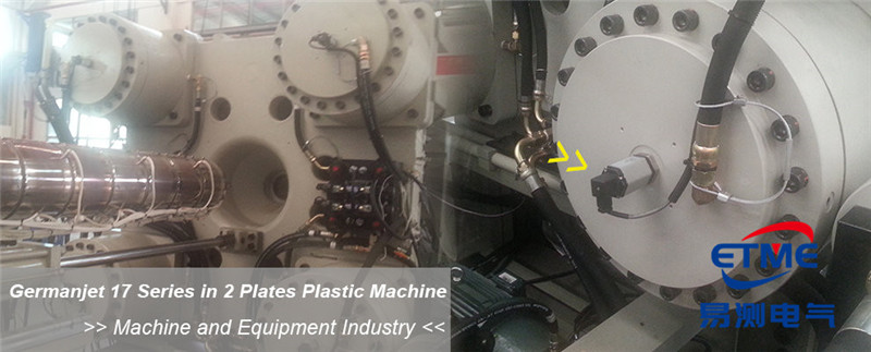
Series 17 Hydraulic Cylinder Integrated Magnetostrictive Displacement Sensor Application Cases
View Details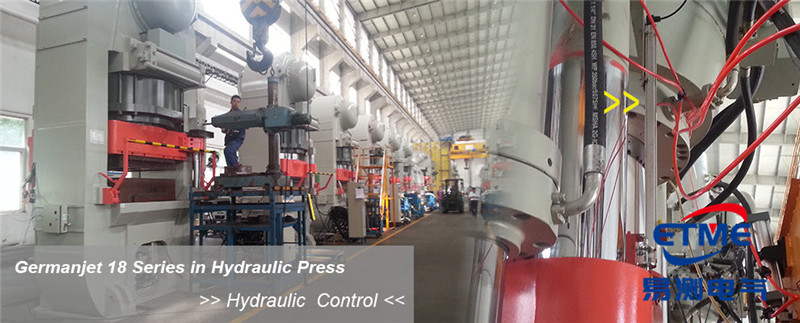
Series 18 Profile Magnetostrictive Displacement Sensor Application Cases
View Details
Multi-Industry Application Cases for Magnetostrictive Displacement Sensors
View Details