
LK 3500-Ton Press: 6 mm Jitter on a 3800 mm Analog Sensor
At 10:30 on 16 December 2013 we arrived at a mould testing shop in Chang'an, Dongguan. On an LK 3500-ton injection moulding machine, a Germanjet 3800 mm analogue-output position sensor was reading 6 mm of jitter. The sensor is rated for micron-level repeatability, so 6 mm is about 0.16 percent of its full stroke. The customer was already preparing to replace it.
Two of our engineers stayed on site from 10:30 to 18:30, together with the LK site engineer and the moulding supervisor. After a full day of testing, the conclusion was one sentence: the sensor was not the problem. The 6 mm came from three on-site issues stacked on top of each other. What follows is the day's troubleshooting in the order it happened, and that route covers almost every analogue sensor pitfall you can meet in the field.

1. Site conditions first
| Item | On-site situation |
|---|---|
| Machine | LK 3500-ton injection moulding machine |
| Sensor | Germanjet 3800 mm analogue output, 0-10 V full scale |
| Symptom | 6 mm jitter on the displayed position reading |
| Date and time | 2013-12-16, 10:30-18:30 |
| People present | Two Germanjet engineers, the LK site engineer, the moulding supervisor |
| Equipment used | HP 34401A 6.5-digit digital voltmeter, 3 V dry battery |
2. Testing one link at a time to find where the reading starts to jump
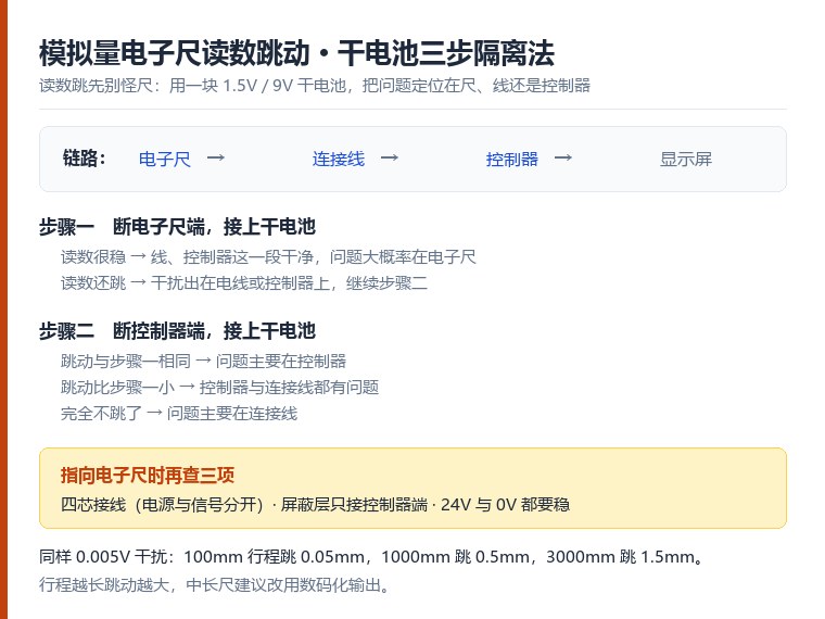
There is only one line of approach: cut the chain "sensor to cable to controller to display" into sections and inject a perfectly stable signal into each one, then watch where the reading starts to jump. The stable signal was a 3 V dry battery, a pure DC source that cannot generate interference itself. Whichever section cannot hold it will show up on the screen immediately.
Step 1 - Measure the sensor itself: 0.19 mm on a 6.5-digit meter
We took the sensor out of the circuit and measured its analogue output directly with the HP 34401A 6.5-digit voltmeter, covering three things: absolute accuracy, repeatability and internal immunity.
The result: voltage jitter stayed within 0.0005 V. On a 3800 mm sensor with a 0-10 V output, that works out to 0.19 mm, and repeatability matched the factory specification exactly.
That removed the biggest suspect: the sensor in our hands was good.
Step 2 - Check the control system: feed the input point with a dry battery
The control system on the machine was the next suspect. We connected a 3 V dry battery straight to the controller input point, without any cable in between.
The reading on the screen was precise, with no jitter. This section was clean too.
Step 3 - 24 V supply: stability is also about 0 V
The sensor and controller were fed from a 24 V supply. Measured output was a stable 24.5 V, and with the pump and peripheral equipment off, the 0 V reference showed no anomaly either.
But this only proved the static state was clean. The moment peripheral equipment moves, the conclusion can flip, and step 5 confirmed exactly that.
Step 4 - The cable: remove the sensor and put the battery on the wire end
This was the critical step of the day.
We disconnected the sensor from the circuit and connected the 3 V dry battery directly to the wire end of the sensor cable. If the cable were clean, the screen should have shown the same steady number as in step 2.
Instead, the screen showed 4 mm of jitter. The cable itself was importing interference.
Together with the LK site engineer we traced the cable run along the duct, and the problem was right there: the sensor cable was bundled with medium-voltage lines and other high-interference lines on the machine. Once we pulled the cable out of the machine and away from those sources, the jitter dropped immediately to about 2 mm.
The interim conclusion was two problems stacked: the cable itself had insufficient immunity, and the routing was wrong.
Step 5 - Peripheral equipment: 0.5 mm from the pump, 2.5 mm from the door
For the final round we eliminated the cable as a variable too: the 3 V battery went straight into the controller input point, with no cable in the path. The reading should have been rock steady.
Switching on the pump produced 0.5 mm of jitter.
Opening or closing the powered door pushed the jitter up to 2.5 mm, and the reading jumped every single time the door moved.
To rule out any human factor, the moulding supervisor watched this test run on site.
At that point the source was no longer inside the sensor, the cable or the controller. It was being injected from the machine's electrical environment: either the machine earthing was poor, or the door drive itself was noisy.
3. The 6 mm was three field problems added together
Putting the five steps together, the 6 mm on this LK machine was not one fault but three field problems stacked:
| No. | Problem | Measured evidence | Contribution |
|---|---|---|---|
| 1 | Sensor cable bundled with medium-voltage and high-interference lines | Battery on the wire end with the sensor removed gave 4 mm; pulling the cable out of the machine cut it to 2 mm | Largest |
| 2 | Poor machine earthing | Battery straight into the controller input, pump running, reading jumped 0.5 mm | Medium |
| 3 | Noisy powered door drive | Same test method, door switching gave 2.5 mm of jitter | Medium |
The sensor was good from start to finish, and the 0.0005 V jitter figure stayed there all day.
4. Do the arithmetic and analogue output stops looking innocent
People often ask: if the sensor resolves 0.19 mm, why would the machine show 6 mm? Because an analogue output is a linear scale, and the longer the stroke, the more length each 1 V represents, so the same voltage interference gets amplified further.
This machine used a 3800 mm stroke with a 0-10 V output: 3800 mm / 10 V = 380 mm per volt, so 1 V represents 380 mm.
Working backwards, to hold 0.5 mm of accuracy the external interference must stay below 0.5 mm / 380 mm per volt, about 0.0013 V.
On site, one door operation produced 2.5 mm of jitter, which converts to 2.5 mm / 380 mm per volt, about 0.0065 V.
The system needed 0.0013 V of cleanliness and was seeing 0.0065 V of interference, roughly five times over. The interference simply covers the accuracy, so 6 mm on screen is no surprise at all.
| Item | Value | Note |
|---|---|---|
| Stroke and output | 3800 mm / 0-10 V | Specification of this machine |
| Scale factor | 380 mm per volt | 1 V represents 380 mm |
| Sensor's own jitter | 0.0005 V, about 0.19 mm | Measured on a 6.5-digit meter, within spec |
| Cleanliness needed for 0.5 mm | No more than 0.0013 V | Threshold |
| Interference from one door operation | 2.5 mm, about 0.0065 V | About five times the threshold |
| Interference from the bundled cable run | 4 mm, about 0.0105 V | Cut to 2 mm once the cable left the machine |
5. Conclusion: do not replace the sensor first
The judgement that day was this: jitter of this kind is usually a matter of analogue selection and field installation, not a failed non-contact sensor. Replacing the sensor is the most expensive step and the easiest one to waste, because a new sensor lands in exactly the same interference environment and jitters just the same.
The advantages of non-contact sensors still hold: high accuracy, fully sealed against dust and water, no mechanical wear. But once you choose an analogue output, everything around it has to be managed as well: cable quality, routing, earthing and the interference level of peripheral equipment. Those items are part of an analogue solution, not optional extras.
Where the stroke is long and the machine's electrical environment is busy, the easier route is a digital output such as CANbus or SSI. Digital output was designed to cover exactly these weaknesses of analogue: the signal is digital, so interference has to be large enough to flip a 0 to a 1 before it affects the reading, and accuracy reaches the 0.005 mm class, at the cost of needing enough controller processing speed.
For this LK 3500-ton machine, the practical sequence is: first take the sensor cable out of the high-interference bundle and run it in its own duct with proper shielding and earthing, then check the machine earthing, and finally assess whether the door drive needs separate treatment. After those three steps the analogue solution can keep working. If the machine needs high accuracy and the interference cannot be cured properly, it is time to consider a digital output.
6. You can run this troubleshooting yourself
The core of the method used that day is a dry battery and two isolation steps: disconnect the sensor end and connect the battery to see whether the reading is steady, then disconnect the controller end and connect the battery, where the three possible results point to the controller, to the controller plus cable, or to the cable alone. The full decision table and how to act on each result are set out in Analogue Sensor Reading Jitter: A Three-Step Dry Battery Isolation Method, which you can follow directly.
Two field details are worth recording separately. First, the cable is the section most easily overlooked: on this LK machine the 4 mm came from the cable, and replacing the sensor without removing it would never have found that. Second, statically clean is not dynamically clean: the 24 V supply was fine with peripheral equipment off, but once the pump and the powered door moved, the 0 V reference was dragged around.
This article is based on the on-site technical record produced by Germanjet engineers for the LK 3500-ton injection moulding machine on 16 December 2013. All measured values are taken from that day's record.
Frequently Asked Questions
Q: The sensor reading jitters. Will a new sensor fix it?
Not first. On this site the sensor's own jitter was only 0.0005 V, about 0.19 mm, comfortably within spec. The 6 mm came from three sources stacked together: cable routing, machine earthing and peripheral equipment. A new sensor in the same interference environment will jitter just the same.
Q: Why does a longer stroke make an analogue sensor jitter more?
An analogue output is a linear scale. The longer the stroke, the more length each 1 V represents, so the same voltage interference is amplified further. On a 3800 mm, 0-10 V sensor, 1 V represents 380 mm, so 0.0065 V of interference becomes 2.5 mm of reading jitter. Short strokes are usually fine on analogue, but long strokes need digital output to hold accuracy.
Q: How do I tell whether interference comes from the electrical environment, the cable or the controller?
Isolate with a dry battery. Connect a 3 V battery straight to the controller input with no cable in between: a steady reading makes the cable the suspect. Then connect the battery to the wire end of the sensor cable: if the reading starts to jump, the cable or its routing is at fault. After both steps, sensor, cable, controller and electrical environment are separated.
Related Products



Related Applications

Multi-Industry Application Cases for Magnetostrictive Displacement Sensors
View Details
Series 16 Hydraulic Rod Magnetostrictive Displacement Sensor Application Cases
View Details
Series 12 General-Purpose Magnetostrictive Displacement Sensor Application Cases
View Details