
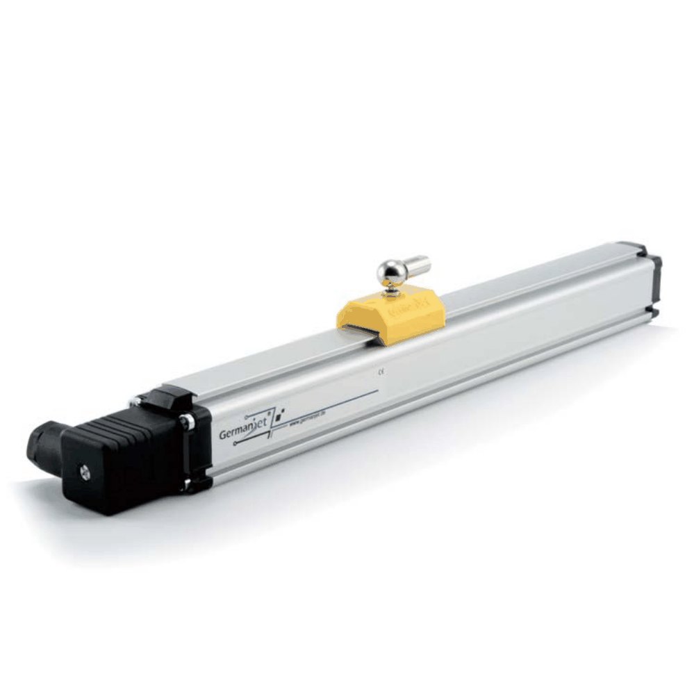
Series 18 external magnetostrictive displacement sensor
External rod/slider/built-in types with analog & Start-Stop output
The Series 18 external magnetostrictive displacement sensor uses non-contact magnetostrictive measurement, offering high reliability, high stability, high accuracy, fast response and a relatively low overall cost. The non-contact design means no positioning maintenance on the mounting face, no recalibration, no wearing parts and no periodic maintenance. The aluminium profile housing meets IP65/IP67 protection standards and operates reliably for the long term in heavily dust-polluted industrial environments. Mechanical forms are rail type and floating type, the latter in ordinary and high floating versions; outputs 180–185 cover voltage, current and Start-Stop. Widely used in injection molding machines, die casting machines, rubber machinery, woodworking and position control. In short, the Series 18 is extremely robust and is the ideal choice for demanding industrial environments.
Product Overview
The Series 18 external magnetostrictive displacement sensor uses non-contact magnetostrictive measurement, offering high reliability, high stability, high accuracy and fast response while keeping overall cost of ownership relatively low. The non-contact design is not only easy to install - more importantly it completely eliminates all measurement error caused by operational wear: no mechanical contact means no wear, and no wear means no periodic maintenance or recalibration.
The aluminium profile housing meets IP65/IP67 protection standards (subject to correct connector selection), ensuring long-term stable operation in harsh industrial environments with heavy dust, oil spray, humidity and condensation. A choice of fixing clips (42.5 mm / 50 mm fixing or insulated clips) provides flexible, simple installation to suit the space constraints of various machines.
Rail type and floating type cover different installation spaces, the floating type in ordinary and high versions, with a high-distance floating magnet available to further increase the gap between magnet and rod. Ball joints compensate misalignment; Start-Stop (order code 183) covers precise switching-point detection. Overall, Series 18 is a very robust and cost-effective general-purpose displacement sensor, and the ideal choice for demanding industrial environments.
Operating Principle
Series 18 uses the non-contact magnetostrictive measurement principle. The sensor body is an aluminium profile housing containing the waveguide and electronics. The external magnet (magnet ring) moves with the measured object and triggers a magnetostrictive strain wave; the electronics convert transit time to absolute position. In the rail type the magnet travels along the profile rail, with concentricity guaranteed by the product itself; in the floating type the magnet floats on the outside of the profile and is available in ordinary and high floating versions, and ball joints can be used. Series 18 does not take cylinder pressure. Either way the measuring core is the same non-contact magnetostrictive principle, ensuring consistent accuracy and reliability.
Typical Applications
Signal Output Types
Analog voltage output
180Dual 0-10 V / 10-0 V analog voltage output, compatible with the analog input channels of most PLCs and controllers.
Analog current output 0-20 mA
1810-20 mA standard analog current output, compatible with 2-wire / 4-wire systems.
Analog current output 20-0 mA
18220-0 mA reverse analog current output for control systems requiring an inverted signal.
Start-Stop digital type
183Start-Stop pulse digital output for applications requiring precise switching point detection; no A/D conversion required.
Analog current output 4-20 mA
1844-20 mA industry standard analog current output with high noise immunity, suitable for long-distance transmission and industrial noise environments.
Analog current output 20-4 mA
18520-4 mA reverse analog current output for control systems requiring an inverted signal.
Technical Specifications
| Measuring Range | 50 ~ 4000+ mm (customisation available) |
|---|---|
| Resolution | Analogue: infinite (controller A/D and supply ripple) |
| Non-Linearity | < ±0.02% FS (min. ±90 μm) |
| Repeatability | < ±0.005% FS |
| Update Time | 0.5 ms (≤1200 mm) / 1.0 ms (≤2400 mm) / 2.0 ms (≤4800 mm) / 5.0 ms (≤7600 mm) |
| Supply Voltage | DC 24Vdc (20.4 ~ 28.8 Vdc) |
| Output Protection | Polarity protection to -30 Vdc / overvoltage protection to 36 Vdc |
| Insulation Resistance | 500 MΩ (DC ground to machine ground) |
| Operating Temperature | -40 °C to +75 °C (90% humidity, non-condensing) |
| Protection Class | IP65 / IP67 (when the connector is properly mated) |
| Housing Material | Anodised aluminium alloy profile |
| Vibration Resistance | 15g (10~2000Hz) / IEC 68-2-6 |
| Shock Resistance | 100 g (single shock) / IEC 68-2-27 (endurance) |
| EMC Compliance | Emission EN61000-6-3 / Immunity EN61000-6-2, EN61000-4-2/3/4/6/8 |
| Magnet / slider types | rail type / floating type / high-distance floating magnet (high floating) |
Models and Output Signals
Dimensions and Wiring Diagrams

18 Series - Matching Dimensions & Accessories
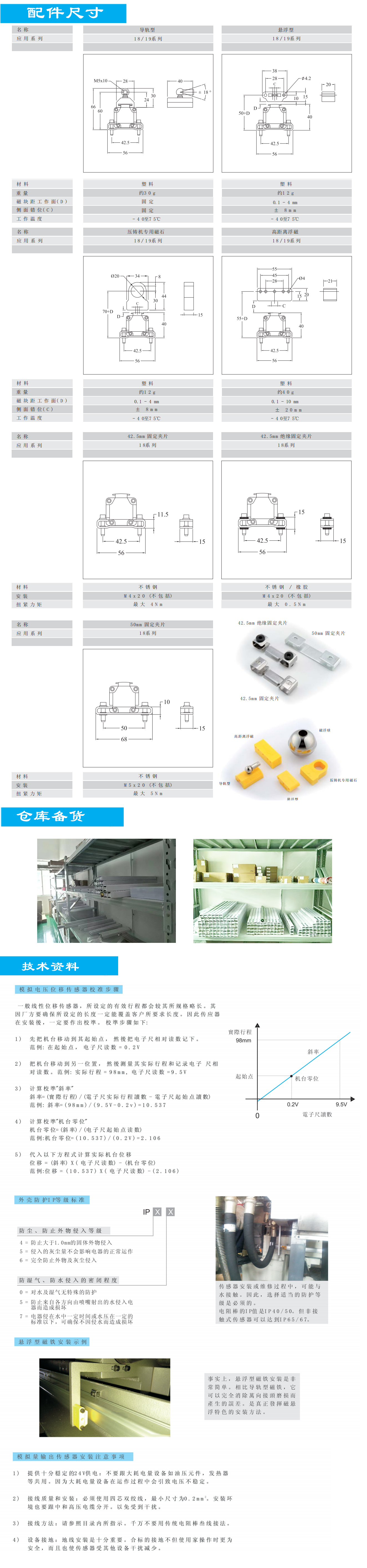
18 Series - Dimensions, Wiring & Electrical Selection
Installation Precautions
- Series 18 is an external type: the magnet ring slides outside the sensing rod with the measured object. Ensure the ring is concentric with the rod and the gap is uniform.
- The rod carries axial load only; neither the rail type nor the floating type may take radial bending or side impact.
- Wiring by output type: 180 analog voltage (load ≥ 5 kΩ); 181 = 0-20 mA, 182 = 20-0 mA, 184 = 4-20 mA, 185 = 20-4 mA (observe loop resistance); 183 Start-Stop digital pulse.
- Ground the signal cable shield at one end only and route it separately from power lines.
- The protection class depends on the model; seal the connector properly for outdoor or humid environments.
- 180 four-pin voltage type: P1 = +24 V, P2 = 10-0 V, P3 = 0-10 V, P4 = 0 V. Controller AI(−) must connect only to sensor 0 V (P4), not to the machine internal earth.
- Swapping supply and signal wires burns the sensor immediately and is outside warranty; use four-core shielded twisted pair of at least 0.2 mm².
- External magnets 1800 951 001–004 (Series 18/19); profile clips 1800 951 007 / 008 (42.5 mm) and 1800 951 009 (50 mm). Confirm air-gap class on the accessory page.
Pricing Notes
Series 18 is a standard external product, with models distinguished by signal output (180 analog voltage / 181 0-20 mA / 182 20-0 mA / 183 Start-Stop / 184 4-20 mA / 185 20-4 mA). Pricing depends on measuring range, output type, rail type / floating type and cable length. Share your stroke and output requirements for a quotation.



Technical Articles

Where to Mount a Magnetostrictive Displacement Sensor: The Wrong Position Moves Both Stroke and Accuracy
Read More
Discontinued and Out of Stock: Finding a Replacement Magnetostrictive Displacement Sensor
Read More
How Much Off-Centre Is Too Much: Telling Coaxiality, Parallelism and Squareness Apart
Read More
Don't Touch the Magnetostrictive Displacement Sensor Yet: Four Layers to Check in Order
Read More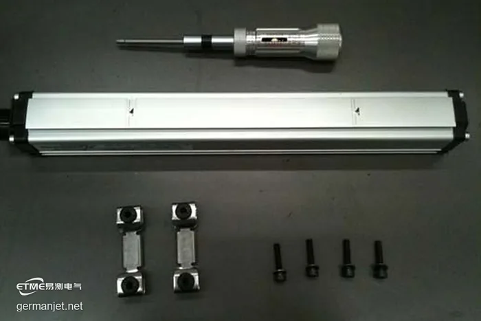
Anti-Vibration Mounting Clips for Injection Moulding Sensors: 42.5 mm Hole Pitch, 3.5 kgf·cm Torque, 13 Steps
Read More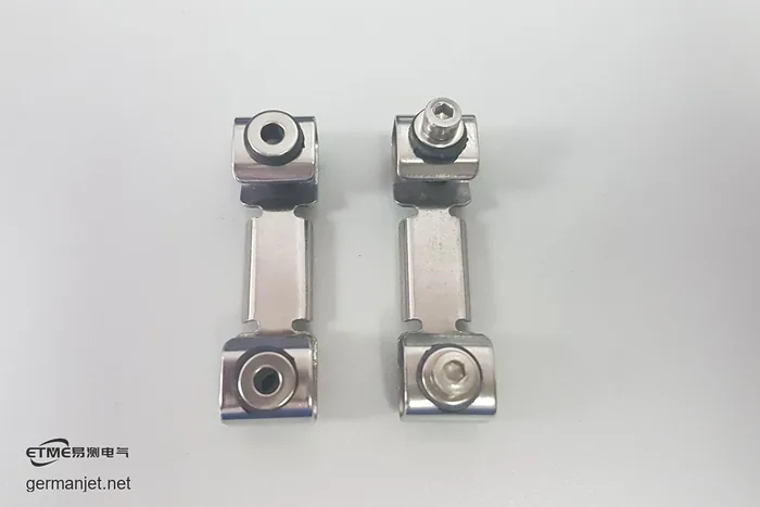
Ten Injection Presses, One Jittering Ejector Sensor: A Thin Mounting Plate Acting as a Tuning Fork
Read MoreRelated Applications

Multi-Industry Application Cases for Magnetostrictive Displacement Sensors
View Details
Series 18 Profile Magnetostrictive Displacement Sensor Application Cases
View Details