Discontinued and Out of Stock: Finding a Replacement Magnetostrictive Displacement Sensor
The magnetostrictive displacement sensor on an ageing machine fails, or the model goes out of production and the original maker stops supplying it. Purchasing takes the nameplate around and every quote comes back empty. The machine itself is fine — the whole job is stuck on one part.
The easiest wrong move is to send the electrical data off the nameplate straight out for quotation. Get the electrical side wrong and you swap it; get the mechanical side wrong and the part is scrap on arrival. Replacement work starts by taking the old unit off and measuring the mechanical interface.
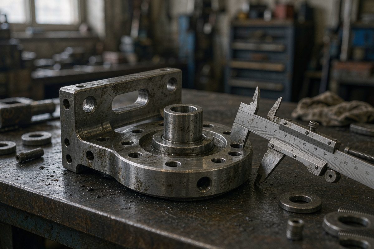
The five mechanical dimensions to measure first
Before dismantling anything, note where it sits: inside the cylinder, external with a rail, or mounted on the machine frame on its own. Where it is mounted decides which series are even candidates.
Flange and hole spacing. Measure centre-to-centre spacing, hole diameter, hole count, and the distance from the flange face to the rod end. If the holes do not line up, nothing else matters.
Rod diameter and end thread. On a built-in type the thread screws into the piston rod, and one size off is one size too many. On an external type, check the rod outside diameter against the rider magnet bore.
Real stroke. Not the rated range on the nameplate — the distance the machine actually travels, plus margin at both ends. On older equipment the real stroke and the original rating frequently disagree. Measure from mechanical stop to mechanical stop.
Pressure rating. For anything mounted inside a hydraulic cylinder this is the critical one. A lower-rated unit substituted for a higher-rated one looks fine for a while, then the rod deforms when cylinder pressure reaches its peak.
Wiring form and exit direction. Connector or flying lead, which side the cable exits, and whether the length reaches the junction box. Skip this and you will be ordering plugs and extensions after delivery.
How to reconstruct the dimensions when there is no drawing
Most sites have no original drawings. Work backwards instead.
The nameplate carries more than expected: model, range, output type, supply voltage, sometimes a year of manufacture. Photograph it clearly. Even with the model discontinued, the series documentation often still exists, and the interface dimensions can be matched from it.
The cylinder itself is a lead. Bore, rod diameter and stroke appear on the cylinder nameplate or in the machine manual. On built-in types the mounting interface is usually tied to the rod specification, so knowing the rod diameter narrows the field.
If nothing can be found, take the old unit off and measure it in full. The rod withdraws, the flange can be laid flat on paper and traced, and the thread can be identified with a pitch gauge. Two hours of careful measurement saves a great deal of returning and reordering.
One reference gets overlooked: if the machine carries several units of the same model and another one still works, that unit is the best physical sample. Take it along rather than a list of numbers.
What must match, and what can flex
| Parameter | Rule | Why |
|---|---|---|
| Mounting flange and hole spacing | Must match | If it does not fit, nothing downstream applies |
| Rod diameter and end thread | Must match | One thread size off and it will not assemble |
| Pressure rating | Equal or higher only | A lower rating deforms at the pressure peak |
| Range | Cover the real stroke with margin | One step up is usually fine; one step down hits the stop |
| Accuracy class | Better is acceptable | Improved accuracy does not conflict with the process |
| Output type | Decided by the controller, not the old unit | An analogue output is useless if the cabinet only has a bus channel |
| Supply voltage | Must fall inside cabinet supply | Site 24 V and 10–30 V wide-range units are handled differently |
| Ingress protection | Not below the original environment | Washdown, oil mist and dust each set a floor |
The two rows most often skipped are pressure rating and output type. Pressure rating is a safety matter, not a performance one. Output type decides whether the new unit can talk to the existing cabinet at all.
The output type is decided by the cabinet, not by the old unit
This is where replacement work most often has to be redone. What the old unit output does not mean the new one must match it — the real constraint is which channel is still free in the control cabinet.
If a spare analogue input is available, use analogue output. Wiring is simplest and the scaling is set in the cabinet. If the cabinet only has a bus trunk, select by bus type and check that node address and baud rate can still accommodate another device.
The reverse also holds: if the old unit was bus-type but that bus port is full and cannot be expanded, an analogue output often lands faster. The three-layer check — mechanical, electrical, parameter — was set out in magnetostrictive displacement sensor parameters: three-layer check when replacing a part. All three have to hold before a substitution is valid.
Three things to redo after installation
- Recalibrate range and zero. The electrical zero and mechanical datum of a replacement do not match the old unit, so it will read offset if fitted and left alone. Follow zero calibration: mechanical datum plus the two-point method — datum first, then the two points.
- Walk the full stroke by hand. Push it slowly from one end to the other and watch continuity and end margin. The replacement may cover more or less stroke than the original, and this step exposes it immediately.
- Re-check the fasteners after running in. A newly fitted flange or bracket loosens after the first few thermal cycles, especially on machines with vibration. Re-torque after one shift, then fold it into the routine inspection.
If the machine had no position measurement at all and this is a retrofit rather than a replacement, the selection logic changes: decide the mounting first, then the model. See retrofitting an old machine: adding position measurement without touching the cylinder.
Field notes for engineers
- Photograph the old unit in three shots before removing it: the mounting position on the machine, the flange face, and the cable exit direction. Refitting from photographs is faster than from written notes.
- When measuring hole spacing, press the flange flat on paper and trace the outline, then measure the tracing. It is more accurate than holding a caliper against the machine, especially where access is awkward.
- The replacement does not have to be the same brand. If the mechanical interface matches, the pressure rating is not lower, and the cabinet can read the output, it will work. Waiting for a specific brand usually costs more time than it saves.
- If no drawing exists, ask the machine builder for the cylinder specification sheet. That is usually easier to obtain than the original unit drawing, and the interface dimensions can be derived from the cylinder data.
Frequently Asked Questions
Q: Can another model from the same brand be substituted directly?
It is more likely to work, but it is not a drop-in. Within one brand, flange form, rod diameter and pressure rating can differ between series, so the five mechanical dimensions still have to be checked one by one. The easiest substitution is usually a different range within the same series, provided the larger range covers the real stroke with margin at both ends.
Q: The replacement has a larger range — does that hurt accuracy?
One step up in range rarely prevents the unit from working, but resolution and absolute accuracy are tied to full scale and will be diluted. If the process requirement was never demanding, there is no practical effect. On precision equipment, recalculate the accuracy figures at the new range before deciding, rather than quoting the old unit numbers.
Q: There is no drawing, only a failed unit. How should the dimensions be taken?
Measure the unit itself, off the machine. Lay the flange on paper and trace the outline before measuring, use a caliper on the rod, a pitch gauge on the end thread, and measure stroke from mechanical stop to mechanical stop rather than trusting the rating plate. If a second unit of the same model is still running on the machine, take it along as the reference sample.
Q: The reading is offset after fitting. Is the replacement wrong?
Do not suspect the part yet. A replacement unit has a different electrical zero and mechanical datum from the original, so an offset is expected and recalibrating range and zero is a required step. If it is still offset after calibration, check whether the mounting is fully seated, whether the stroke is properly covered, and whether the output type actually matches the cabinet channel.
Related Products



Related Applications

Multi-Industry Application Cases for Magnetostrictive Displacement Sensors
View Details
Series 18 Profile Magnetostrictive Displacement Sensor Application Cases
View Details
Series 19P External Rod Process Displacement Sensor Application Cases
View Details