
Retrofit a Magnetostrictive Displacement Sensor Without Stripping the Cylinder
A parallel external mount plus a magnet slider on the rod end gives an absolute signal, so adding position measurement to legacy equipment usually leaves the cylinder untouched. “Whether the cylinder must be opened” is the watershed of feasibility; opening it means downtime, a clearance bore, reassembly and pressure testing — high duration and high risk. In most cases mount an external magnetostrictive displacement sensor parallel to the cylinder, connect the magnet slider through a bracket to the piston-rod end or the moving beam, and obtain an absolute-position signal of the same class as an in-cylinder type. This article covers feasible paths, mounting constraints, signal interfacing and acceptance. The external product is explained in Series 18 External Explained: Matching Profile-Mounted and Follower Structures.
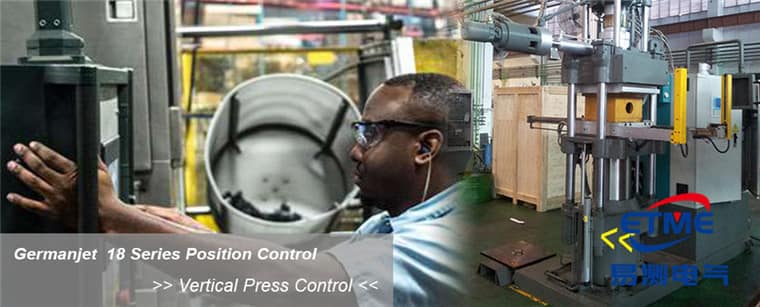
Three paths that leave the cylinder untouched
- Path 1: external parallel mounting. Fix the sensor along the cylinder axis on the barrel or the machine frame; connect the magnet carriage with a bracket to the piston-rod end. This suits the great majority of sites with parallel mounting space and is the preferred scheme. Products include Series 18 external and Series 19P external.
- Path 2: measure the moving part rather than the cylinder. If the cylinder neighbourhood is crowded, measure the driven carriage, beam, table or other end moving part instead. The advantage is avoiding the space fight around the cylinder, and measuring the end position that is actually of interest (transmission backlash is then included in the measuring chain); the disadvantage is that an extra mounting datum is needed.
- Path 3: flexible long-stroke routing. When the stroke is long, the path is not straight and a rigid rod cannot be installed, a flexible-rod model can be routed along a feasible path; see Series 19F flexible long-stroke. Boundary conditions for long stroke are in Long-Stroke Selection (2 m and Above).
Only when none of the three paths is feasible (no external space at all, or protection requirements forbid exposed parts) should a shutdown retrofit of the cylinder for in-cylinder mounting be considered; then follow Cylinder Bore Machining Requirements, with a minimum piston-rod bore ≥12.7 mm. The overall difference between external and in-cylinder types is in Choosing Among the Cylinder-Integrated 13 and the External 18 / 19P / 19F.
Six items that must be measured before the retrofit
- Actual maximum stroke: run the full stroke by hand or jog and measure it; do not copy the nameplate. Ordered stroke must still add two-end margin; the calculation is in Practical Selection Calculations;
- Usable mounting length: clear space along the axis, including room for the electronics head and connector plug-in;
- Mounting datum: whether a reliable face parallel to the motion direction exists; parallelism error will bind the magnet slider;
- Motion interference: conflict over the full stroke with pipework, guards, stops or access ways;
- Site environment: wash-down, dust, oil mist, high temperature and vibration, from which IP65 / 67 / 68 / 69K and vibration class are set. For severe duty see Series 13 mobile hydraulics (IP69K, 25 g vibration, 100 g shock);
- Existing controller interfaces: available analog channels, fieldbus type and free nodes.
Signal interfacing: replace the old sensor or add a channel
| Existing situation | Recommended output | Change on the control side | Notes |
|---|---|---|---|
| Was a potentiometer resistive scale (voltage-divider output) | 0-10 V | Minimal; reuse the original channel | Check range mapping and zero direction |
| Was a 4-20 mA transmitter signal | 4-20 mA | Minimal | Check loop load resistance and supply method |
| No position measurement; only travel switches | 4-20 mA or fieldbus | Need to add an AI or a bus node | Switch-point logic can be replaced by software comparison |
| Was an incremental encoder | SSI or fieldbus | Program change; drop homing | Absolute position can omit the homing move |
| CANopen / Profibus network already present | Matching fieldbus type | Add a slave and configure | Check node margin and bus load |
| EtherCAT / PROFINET network already present | Matching fieldbus type | Import the description file and configure | Confirm cycle-time margin |
A replaced contacting-type sensor on old machines is only the comparison object, replaced by a magnetostrictive displacement sensor. Analog schemes can use Series 191 analog; the overall interface framework is in Selecting a Magnetostrictive Displacement Sensor: 4-20 mA Analog or CANopen Fieldbus?; the specific differences when replacing a resistive scale are in Magnetostrictive vs. Potentiometer / Resistive Scale: Life, Failure Modes and Total Cost of Ownership. If the original discrete interlock must still be kept after the retrofit, a position-comparison output in the controller can replace it and reduce field wiring.
Four common mechanical-installation pitfalls
- Insufficient bracket stiffness: a long-cantilever thin-plate bracket deflects under shock, producing a load-dependent reading error that calibration cannot remove; check bracket section and fixing points against the load.
- Parallelism not adjusted: if the sensor axis is not parallel to the motion direction, the magnet slider sees a radial force along the stroke — extra friction at best, seizure at worst. After installation, push the full stroke by hand and confirm there is no binding.
- Magnet connection too rigid: a small angular and lateral offset should be allowed between slider and moving part (a floating coupling may be used); a fully rigid connection transfers all mechanical deviation into the sensor.
- Poor cable routing: cable that moves with the part must run in a drag chain and meet the minimum bend radius; the fixed end needs strain relief to avoid long-term bend fatigue.
The full external-mounting specification is in External Installation: Getting Bracket Rigidity, Parallelism and slider Float Right; commissioning and zero setting are in Installing Magnetostrictive Displacement Sensors in Practice: Position Magnet, Zero Point, Noise Immunity.
Retrofit acceptance
- Power down and up once each; confirm that the absolute-position reading is consistent and that no homing is required;
- Run the full stroke at low speed and record the curve; check for steps, jumps and binding;
- Position round-trip at 10%, 50% and 90% and check repeatability;
- Run under load and watch whether the reading changes with load (a change is bracket deflection);
- Remeasure with drives and other equipment at full load and confirm there is no interference jump; troubleshooting is in Troubleshooting Magnetostrictive Displacement Sensors: Inaccurate Readings, Jumps, No Output.
Practical tips for engineers
- For in-cylinder mounting, piston-rod bore lower limit is ≥12.7 mm (Ø10 rod). Series 17 also has a Ø13 mm through-hole + M18×1.5 on the cylinder cap; Series 16 uses Ø18G7. Do not mix pressure ratings: Series 16/16R is 350 bar working / 530 bar peak, Series 17/17EX is 350/600 bar, Series 19 in-cylinder is 300/600 bar.
- The sensor rod should be protected against wear inside the cylinder.
- Series 19 in-cylinder types are rated 300 bar with a 600 bar peak; use these figures for selection and pressure testing.
Frequently Asked Questions
Q: What ways are there to add position measurement without opening the cylinder?
Three paths: an external sensor mounted parallel to the cylinder axis, with the magnet slider connected to the piston-rod end — this is preferred; measuring the driven carriage, beam or other end moving part, which avoids the space fight around the cylinder; a flexible-rod model routed along a feasible path when the stroke is long and the path is not straight.
Q: What data must be measured before the retrofit?
Six items: actual maximum stroke (do not copy the nameplate), usable mounting length along the axis, whether a reliable face parallel to the motion direction exists, motion interference over the full stroke, site environment (wash-down, dust, oil mist, high temperature, vibration), and the controller’s existing analog channels and fieldbus margin.
Q: What goes wrong most easily on an external retrofit?
Bracket stiffness and parallelism. A long-cantilever thin-plate bracket deflects under shock, producing a load-dependent reading error that calibration cannot remove; if the sensor axis is not parallel to the motion direction the magnet slider sees a radial force along the stroke. After installation, push the full stroke by hand to confirm there is no binding, and remeasure under load.
Q: What must be changed in the program when moving from an incremental encoder to absolute position?
Drop the homing sequence. After the change to absolute position, the correct position is available at every power-up; if the program still retains a homing move it wastes cycle time and may hit a stop. Also write ordered stroke, zero offset, range mapping and magnet type into the machine file.
Related Products



Related Applications

Multi-Industry Application Cases for Magnetostrictive Displacement Sensors
View Details
Series 18 Profile Magnetostrictive Displacement Sensor Application Cases
View Details
Series 19F Flexible Process Displacement Sensor Application Cases
View Details