Above 2 m, Take a Flexible Magnetostrictive Displacement Sensor Rod or Split the Stroke
Once stroke exceeds 2 m, the selection logic for a magnetostrictive displacement sensor is entirely different from short stroke: absolute error, update rate, mechanical stiffness, transport and installation all become constraints at once. Non-linearity is stated as % FS, so absolute error grows with range; update rate falls as range increases and may no longer satisfy a high-speed closed loop; a rigid rod becomes harder to transport and install as it lengthens, and the site may not have a straight clearance space. Two paths are feasible: measure the whole stroke with a flexible-rod long-stroke model, or segment and splice the measurement, synthesising it in the controller. This article gives the boundaries and engineering practice of both paths; the flexible long-stroke product is explained in 19F Flexible Long-Stroke Explained.
Four changes that come with long stroke
- Absolute error scales with range: typical non-linearity <0.02% FS is ±0.02 mm on 100 mm and ±0.8 mm on 4000 mm. This is a mathematical result of the range base, not a drop in product performance. If the process allowance is given in millimetres, convert before selecting; the method is in The Three Accuracy Terms.
- Update rate falls: the round-trip time of the stress wave on the waveguide increases with length, so the measuring period lengthens. Long-stroke models have a markedly lower update rate than short-range models; high-speed reciprocating closed loops must be calculated in advance — see Matching Response Time and Refresh Rate to the Control Cycle.
- Mechanical stiffness and self-weight sag: beyond a certain length the sag of a rigid rod under its own weight cannot be ignored; horizontal mounting needs intermediate supports, and those supports must not interfere with magnet travel.
- Transport and installation: a rigid bar several metres long is easily deformed in transit, and the site often has no equal-length straight withdrawal space.
Path 1: whole-stroke measurement with a flexible rod
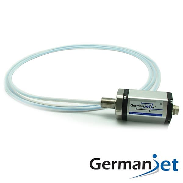
Flexible long-stroke models (for example Series 19F flexible long-stroke) place the waveguide in a flexible sheath that can be coiled for transport and routing. That solves the transport and installation-space problem of a rigid rod and also avoids the interference of intermediate supports. Applications include mill roll-gap, water-gate hoists, large silos and long-stroke lifting mechanisms. Engineering points: the minimum bend radius of the sheath must be observed — a too-sharp bend changes the waveguide loading; clamps must be spaced evenly to avoid local hanging and swing; the magnet slider connection to the moving part should allow a small angular deviation and must not be forced. Typical applications are in Metallurgical Rolling Mill Roll Gap Control: Long-Stroke Position Solutions and Water Gates and Hoists: Maintenance-Free Outdoor Long-Stroke Measurement.
Path 2: segmented spliced measurement
A segmented scheme divides the total stroke into several sections, each covered by a shorter-range sensor, with an overlap between sections; the controller selects the valid section from the present position and continues the reading. The advantage is that each section is short, absolute error is small and update rate is high; the cost is more complex continuation logic and extra calibration and verification work.
Engineering points:
- The overlap must be sufficient: adjacent sections should have a clear overlapping stroke, so that hunting near the switch point does not cause the section number to jump repeatedly;
- Switching must have hysteresis: use different switch thresholds for up and down travel to prevent boundary oscillation;
- Inter-section offset calibration: read both sections together in the overlap, compute a fixed offset and write it into the controller; do this once at installation and recheck after a major overhaul;
- Failure detection: if any section has no output or a reading out of range, output a clear fault flag rather than silently switching to the adjacent section;
- Synchronous sampling: multiple sections should share one fieldbus and use a synchronisation mechanism, so that inconsistent sampling instants do not cause a splice jump. Multi-sensor calibration is in Synchronizing Multiple Sensors.
Comparison of the two paths
| Aspect | Flexible-rod whole-stroke measurement | Segmented spliced measurement |
|---|---|---|
| Measuring chain | One unit covers the full stroke | Several units spliced; synthesised in the controller |
| Absolute error | Converted on full-range % FS; grows with stroke | Converted on single-section range; absolute error is small |
| Update rate | Falls with length | Higher on each section |
| Installation complexity | Low; can be coiled for transport; observe minimum bend radius | High; needs bracket alignment and inter-section calibration |
| Controller effort | No extra logic | Needs continuation, hysteresis and fault-decision logic |
| Effect of a fault | A single-point failure loses the whole stroke | A single-section failure affects only that section; local degraded running is possible |
| Spare parts | Must be stocked to the customised length | Same-specification short-range units can be shared spares |
| Calibration and maintenance | One full-stroke calibration | Inter-section offsets need periodic recheck |
| Suited to | Gates, mills, long-stroke lifting, position | Very long tracks; accuracy tighter than a single full-range unit can achieve |
Selection decision order
- First convert absolute error as total stroke × non-linearity and compare with the process allowance; if it meets the allowance, choose whole-stroke measurement and do not go to segmentation for convenience;
- If it does not meet, assess whether the section that actually needs high-accuracy measurement can be shortened (high accuracy only on the critical section);
- Only then consider segmentation, and include controller logic and calibration cost;
- Check whether the update rate meets the control cycle;
- Check installation space, support method and transport feasibility;
- Fix the output. Prefer fieldbus for multi-section schemes so that synchronisation and diagnostics are available; see Series 194 CANopen. For a single analog unit see Series 191 analog; for external mounting see Series 18 external. The full stroke and mounting calculation is in Practical Selection Calculations.
Practical tips for engineers
- Series 19F flexible types must be supported inside a straight or bent guide pipe of non-ferromagnetic material.
- With a 10 mm ID flange: pipe OD must be <10 mm and ID >8 mm; with a 12.7 mm ID flange: OD <12.7 mm and ID >8.5 mm.
- Guide-pipe length: stroke + 150 mm when stroke <8000 mm; stroke + 230 mm when stroke >8000 mm. The flexible-rod jacket is PTFE-coated stainless steel and may be used in heavily contaminated environments.
Frequently Asked Questions
Q: Why does the accuracy of a long-stroke sensor appear to get worse?
Non-linearity is a percentage of full scale: 0.02% FS is ±0.02 mm on 100 mm and ±0.8 mm on 4000 mm. This is a mathematical result of the range base, not a drop in product performance. Convert % FS to millimetres on this project’s range before selecting.
Q: What should I watch when installing a flexible long-stroke model?
The minimum bend radius of the sheath must be observed; a too-sharp bend changes the waveguide loading. Space clamps evenly to avoid local hanging and swing. The magnet-carriage connection to the moving part should allow a small angular deviation and must not be forced. Before installation, dry-run the actual path on the floor.
Q: How can a segmented spliced scheme be made stable?
Five points: provide sufficient overlapping stroke between adjacent sections; switch with hysteresis, using different thresholds for up and down travel; calibrate a fixed inter-section offset in the overlap; output a clear fault flag if any section fails rather than switching silently; put multiple sections on the same fieldbus and use a synchronisation mechanism so that sampling instants do not disagree.
Q: When is a segmented scheme actually needed?
First convert absolute error as total stroke times non-linearity; if it meets the allowance, choose whole-stroke measurement. If it does not, first assess whether the section that needs high-accuracy measurement can be shortened; only then consider segmentation, and include the cost of controller continuation logic and inter-section calibration.
Related Products


Related Applications

Multi-Industry Application Cases for Magnetostrictive Displacement Sensors
View Details
Series 18 Profile Magnetostrictive Displacement Sensor Application Cases
View Details
Series 19D Split-Type Process Displacement Sensor Application Cases
View Details