
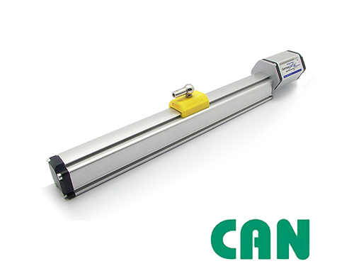
Series 19 CANopen bus magnetostrictive displacement sensor
CANopen DS-301 V3.0, 6-pin D60, 20–1000 kbit/s
The Series 19 CANopen version is based on the CAN 2.0A/2.0B physical layer and the CANopen CIA DS-301 V3.0 device profile, with a 6-pin D60 male connector, and connects directly to a CANopen network as a position slave. It provides an EDS device description file and LED diagnostic display, and supports bus/serial network topologies. IP67 protection.
Product Overview
The Series 19 CANopen version combines high-precision magnetostrictive measuring technology with the CANopen industrial fieldbus, based on the CAN 2.0A / 2.0B physical layer.
Compliant with the CANopen CiA DS-301 V3.0 communication profile (CANbasic mode compatible with CAN 2.0A) and supplied with a standard EDS device description file for seamless integration into any CANopen master.
Supports PDO real-time position publishing and SDO parameter configuration. 6-pin D60 male connector, IP67 protection. Transmission rate up to 1000 kbit/s (cable length < 25 m), suitable for demanding sites in construction machinery, metallurgy and port machinery.
Operating Principle
Building on the standard magnetostrictive measurement principle, the Series 19 CANopen version implements the CANopen protocol stack in the electronics module (CIA DS-301 V3.0 communication profile, compatible with CANbasic CAN 2.0A). Position data is published cyclically as PDOs (Process Data Objects) and parameters are configured via SDOs (Service Data Objects), transmitted on a standard CAN bus through a 6-pin D60 male connector. Built-in LED diagnostics simplify on-site troubleshooting.
Typical Applications
Technical Specifications
| Ordering Code | 194 |
|---|---|
| Output | CANbus digital output |
| Measured Data | Linear displacement |
| Data Format | CANopen: CiA standard DS-301 V3.0; CANbasic: CAN 2.0A |
| Transmission Rate | 1000 / 800 / 500 / 250 / 125 / 50 / 20 kbit/s (cable length <25 m to <2500 m) |
| Resolution - Position | CANopen: 5μm / 2μm;CANbasic: 5μm / 2μm |
| Resolution - Velocity | CANopen: 0.5mm/s / 0.2mm/s;CANbasic: 1.0mm/s / 0.1mm/s |
| Repeatability | < ±0.001% of full scale (min. ±2.5 µm) |
| Non-Linearity | < ±0.01% of full scale (min. ±40 µm) |
| Update Time | 0.5ms(≤1200mm) / 1.0ms(≤2400mm) / 2.0ms(≤4800mm) / 5.0ms(≤7600mm) |
| Power Supply | +24Vdc(20.4 – 28.8Vdc) |
| Input Protection | Polarity protection to -30 Vdc, overvoltage protection to 36 Vdc |
| Power Consumption | 100 mA (depending on measuring range) |
| Dielectric Strength | 500 Vdc (DC ground to machine ground) |
| Connector Options | 6-pin D60 male connector |
| Operating Temperature | -40 to +75 °C, 90% humidity, non-condensing |
| Protection Class | IP67 (when the connector is properly mated) |
| Vibration | 15 g / 10-2000 Hz / IEC standard 68-2-6 |
| Shock Resistance | 100 g (single shock) / IEC standard 68-2-27 (endurance) |
| EMC Compliance | Emission EN61000-6-3, immunity EN61000-6-2, EN 61000-4-2/3/4/6/8 |
Models and Output Signals
Dimensions and Wiring Diagrams
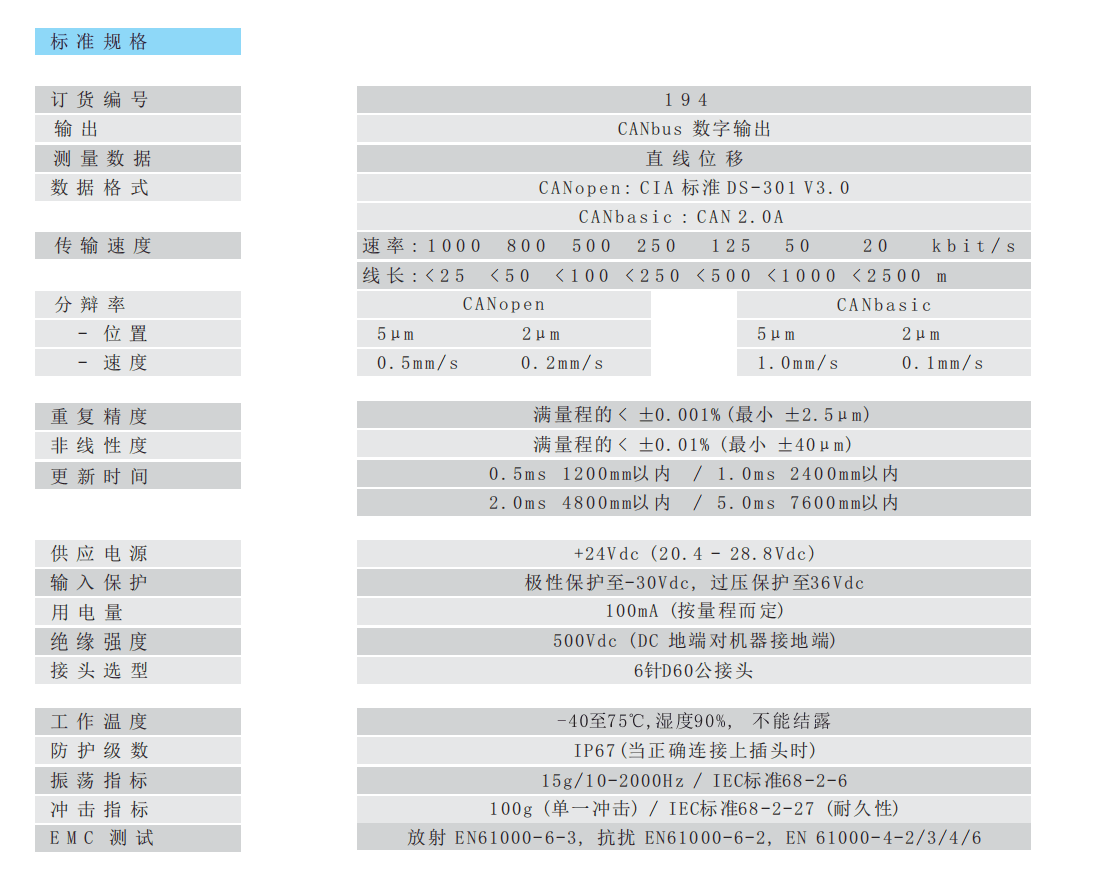
194 CANopen standard specification table
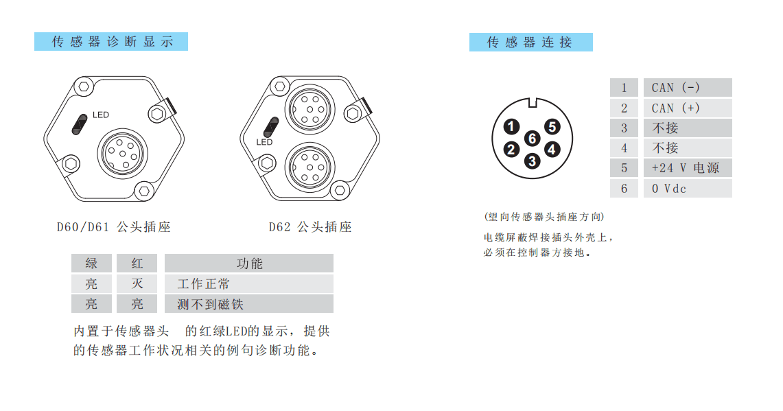
D60/D61/D62 socket diagnostic LED and 6-pin assignment
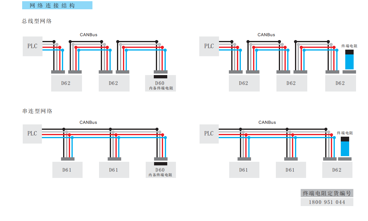
CANbus bus type / daisy-chain network topology
Installation Precautions
- On a CANopen network the node ID and baud rate must be configured correctly and 120 Ω terminating resistors must be fitted at both ends of the bus (order number 1800 951 044).
- D60/D62 6-pin assignment (looking at the sensor head socket): 1 = CAN (−) / 2 = CAN (+) / 3 = not connected / 4 = not connected / 5 = +24 V supply / 6 = 0 Vdc. The cable shield must be soldered to the connector shell and grounded at the controller side.
- The sensor head has built-in red/green LED diagnostics: green on / red off = normal operation; green on / red on = no magnet detected. Diagnostic functions are provided for fast on-site troubleshooting.
- Supported network topologies are bus type (D60 with built-in terminating resistor) and daisy-chain type (D61/D62); a terminating resistor must be fitted at the end. Use shielded twisted pair (CAN_H / CAN_L) and avoid parallel runs with high-power lines.
- Import the EDS file into the master and confirm the PDO mapping and sampling period.
- Regardless of the output interface, the physical installation of Series 19 must comply with the following: the ring magnet must not touch the rod; when built into a cylinder, piston-rod bore ≥12.7 mm (Ø10 rod); Series 19 in-cylinder is 300 bar working / 600 bar peak — never exceed that series peak; the rod must be protected against wear.
- D60/D70 mating cables: 1800 951 010–013 (straight / 90°). CAN terminator 1800 951 044.
Pricing Notes
The price of the Series 19 CANopen bus version depends on the communication protocol, measuring range and mounting method. Please provide the master brand and bus requirements to obtain a quotation.



Technical Articles
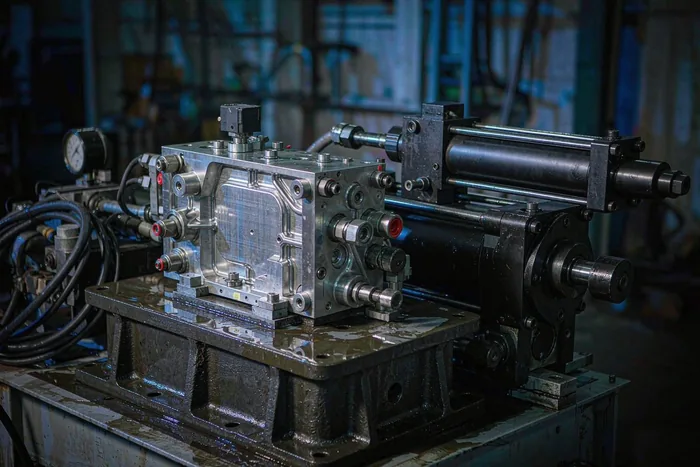
Two Feedback Loops, Not One: Why Spool Position and Cylinder Position Are Measured Separately
Read More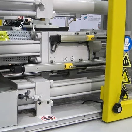
SSI Displacement Sensor Jumps After a Longer Cable: Drop the Clock to Match Length
Read More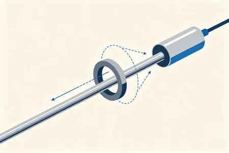
Magnetostrictive Displacement Sensor Principle: Open vs Closed Magnet Ring
Read More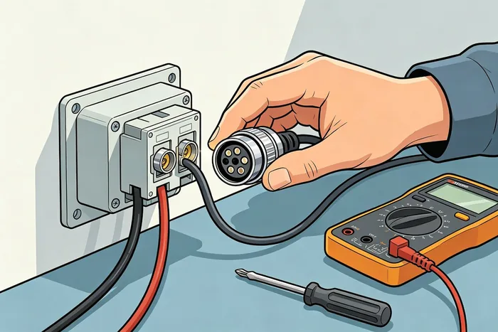
Displacement Sensor Wiring Guide: Installation Steps, Principles and Four-Wire Hook-Up
Read More
Magnetostrictive output signals compared: eight interfaces and their trade-offs
Read More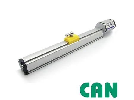
Magnetostrictive Displacement Sensor Fieldbuses: CANopen vs Profibus for Position Feedback
Read MoreRelated Applications

Series 19D Split-Type Process Displacement Sensor Application Cases
View Details
Series 19F Flexible Process Displacement Sensor Application Cases
View Details
Series 19H Cylinder-Integrated Process Displacement Sensor Application Cases
View Details