Displacement Sensor Wiring Guide: Installation Steps, Principles and Four-Wire Hook-Up
Wiring a displacement sensor is not hard, but the first installation usually fails on one of three things: mounting, the four-wire rule, or a shorted signal return. This guide covers installation steps, the wiring principle and the four-wire 4-20 mA hook-up for a magnetostrictive displacement sensor.
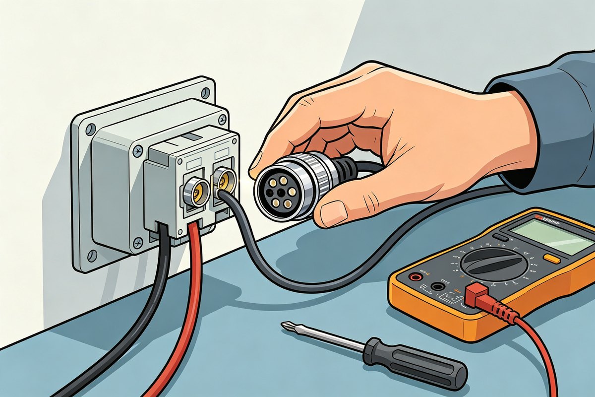
Installation steps (four)
- Mount the sensor — bracket fixed, rod straight, magnet ring centred on the rod. On a long stroke, add a mid-support so the rod cannot whip.
- Set the stroke — the magnet must stay inside the measuring range in every position; never let it hit the ends.
- Route the cable — away from heating, water and moving parts; leave a service loop. Never bundle the cable with hydraulic lines or power cables.
- Wire and power up — follow the pin table for the series and connector, then power on and check the reading moves smoothly.
The wiring principle: separate supply and signal first
Before touching terminals, decide which pair is supply and which is signal. On Germanjet analogue magnetostrictive sensors the two are fully independent — the supply is 24 V (and 0 V), the signal is 4-20 mA or 0-10 V on its own pair. That separation is the four-wire rule.
Digital outputs — Start/Stop, SSI, CANopen, Profibus-DP, EtherCAT, Profinet — are wired to the pin definition of the relevant interface instead. Pin number, wire colour and screen handling are all shown in the connector pin diagram for that series, so compare before you wire.
The four-wire rule in one line: supply to supply, signal to signal, and nothing in between.
Four-wire 4-20 mA hook-up
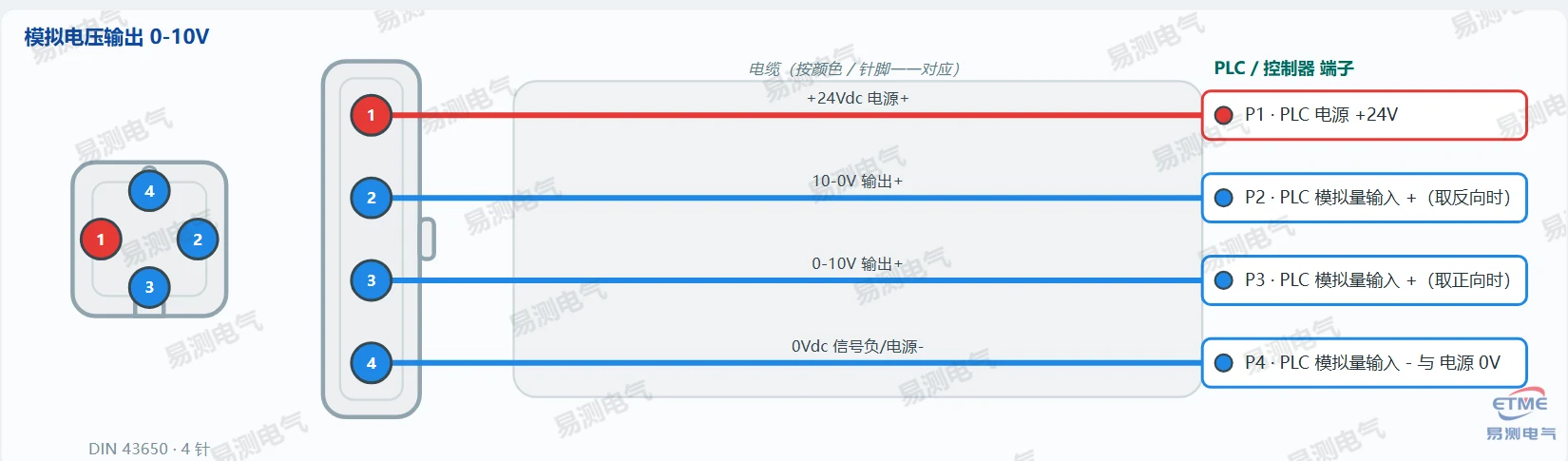
- Terminal 1 / 2: 24 V DC supply (+ and 0 V) — power the sensor from a stable 24 V source.
- Terminal 3 / 4: signal + and signal − — connect to the PLC analogue input.
- Never tie signal − to supply 0 V. They look similar but joining them creates a ground loop and shifts the reading.
- Shield: earth at the controller end only.
Three common traps
- Signal minus tied to 0 V — the most common wiring fault; the reading shifts or wanders.
- Supply ripple — a dipping 24 V makes the 4-20 mA output jump; fix the supply before blaming the sensor.
- Shield earthed at both ends — creates a ground loop; earth one end only.
- Connector not locked home — a circular connector must be turned all the way to its stop; a loose one gives intermittent signal loss that looks like a sensor fault.
- Wrong cable on the signal — use screened twisted pair for 4-20 mA, never a plain single-core wire.
- Hot plugging — power off before removing a connector; unplugging live burns the pins.
Pin tables for every Germanjet series are in the complete wiring reference. If the reading jumps after correct wiring, use the dry battery isolation method.
Frequently Asked Questions
Q: What does four-wire mean in practice?
Two terminals carry the 24 V supply and two carry the signal, fully separate. Never join the signal minus to the supply 0 V.
Q: Where do I earth the shield?
At the controller end only. Earthing both ends creates a ground loop that makes an analogue reading wander.
Related Products
Related Applications

Multi-Industry Application Cases for Magnetostrictive Displacement Sensors
View Details
Series 12 General-Purpose Magnetostrictive Displacement Sensor Application Cases
View Details
Series 18 Profile Magnetostrictive Displacement Sensor Application Cases
View Details