Magnetostrictive Displacement Sensor: Wiring Diagrams for All Series
Germanjet magnetostrictive displacement sensor wiring guide — pin definitions and wiring for the whole range (Series 12 / 13 / 16 / 17 / 18 / 19 and the 7-pin D70 plug), covering analogue voltage/current, Start/Stop, SSI, CANopen, CANbus, Profibus-DP and EtherCAT/Profinet. Every magnetostrictive displacement sensor wiring diagram is drawn sensor connector → cable → controller terminal, with the not-connected (NC) pins marked, so a site engineer can see at a glance how to wire a displacement sensor without miswiring it. Always wire to the product label and the order code.
⚠️ Wiring golden rules — read first. A wrong connection destroys the sensor and is not covered by warranty.
- Never reverse supply and signal. Do not connect +24 Vdc to a signal output (P2/P3 or Output1/Output2) and do not connect 0 V to a signal pin. The sensor is destroyed immediately and the damage is outside warranty. Correct: +24 V to the supply pin, 0 V to the supply ground pin, signal to the signal pin.
- Supply range: the supply must be 20.4 – 28.8 Vdc (nominal +24 Vdc), low ripple and adequate power (allow ≥40 mA per sensor).
- Use four-core (or more) twisted-pair screened cable, conductor cross-section ≥ 0.2 mm². Our analogue output is four-wire (supply and signal fully separate). Never tie the signal minus to the supply 0 V as in a three-wire scheme — the reading becomes unstable and accuracy drops.
- The negative (-) analogue input of the controller may only go to the sensor 0 V (P4). Do not connect it directly to machine 0 V or to earth.
- Screen earthed at one end only: the cable screen goes to the connector shell and is earthed at the controller end, left open at the sensor end, to avoid a ground loop.
- Confirm the output type before wiring (voltage / current / SSI / CAN / fieldbus). Pin functions differ between output types — always check the table below.
Series 18 magnetostrictive displacement sensor wiring (external, universal · analogue / start-stop)
Non-contact magnetostrictive measurement in an extruded aluminium housing, IP67, for general external mounting on machinery. Analogue voltage/current and Start/Stop digital outputs are available in the standard 4-pin oil-proof plug (DIN 43650), with optional 5-pin M12 A-coded, D60 6-pin M16 and S32/S15 8-pin connectors — check the order code.
▸ Analogue voltage output 0-10 V / 10-0 V (DIN 43650)
| Pin | Function | To controller |
|---|---|---|
| P1 | +24 Vdc supply + | PLC supply +24 V |
| P2 | 10-0 V output + | PLC analogue input + (reverse direction) |
| P3 | 0-10 V output + | PLC analogue input + (forward direction) |
| P4 | 0 Vdc signal minus / supply minus | PLC analogue input - and supply 0 V |
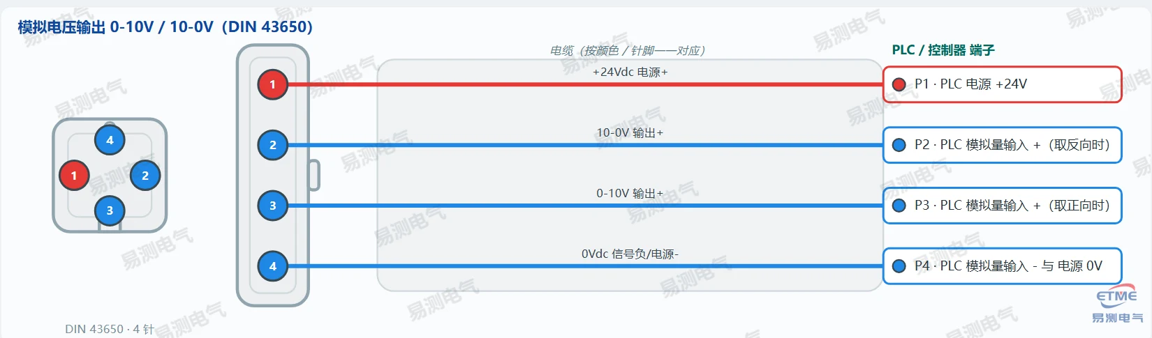
📌 Dual output: P3 = 0-10 V (forward travel output +), P2 = 10-0 V (reverse travel output +), both sharing P4 (0 V) as negative / supply ground. One channel is usually enough: take P3 → AI+ for forward, P2 → AI+ for reverse, and wire P4 to AI- and to supply 0 V.
▸ Analogue current output 4-20 mA / 0-20 mA (DIN 43650)
| Pin | Function | To controller |
|---|---|---|
| P1 | +24 Vdc supply + | PLC supply +24 V |
| P2 | 4-20 mA output + | PLC analogue input + |
| P3 | Signal - , 4-20 mA output - | PLC analogue input - and supply 0 V |
| P4 | 0 Vdc supply minus | PLC supply 0 V |
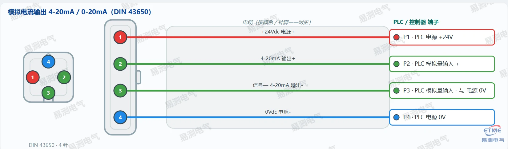
📌 4-20 mA is an active four-wire output (supply and signal fully separate): P1 = +24 V, P2 = 4-20 mA output +, P3 = signal - 4-20 mA output -, P4 = supply 0 V. P3 and P4 are not linked inside the sensor — all four conductors are used. At the PLC, P3 goes to analogue input AI- and P4 to supply 0 V; both must be wired, neither may float.
▸ 5-pin M12 A-coded · single analogue output (voltage or current)
| Pin | Function | To controller |
|---|---|---|
| P1 | +24 Vdc supply + | PLC supply +24 V |
| P2 | Signal output + | PLC analogue input + |
| P3 | 0 Vdc supply minus / signal ground | PLC supply 0 V / AI- |
| P4 | Not connected / N.C. | |
| P5 | Signal ground | PLC analogue input - |
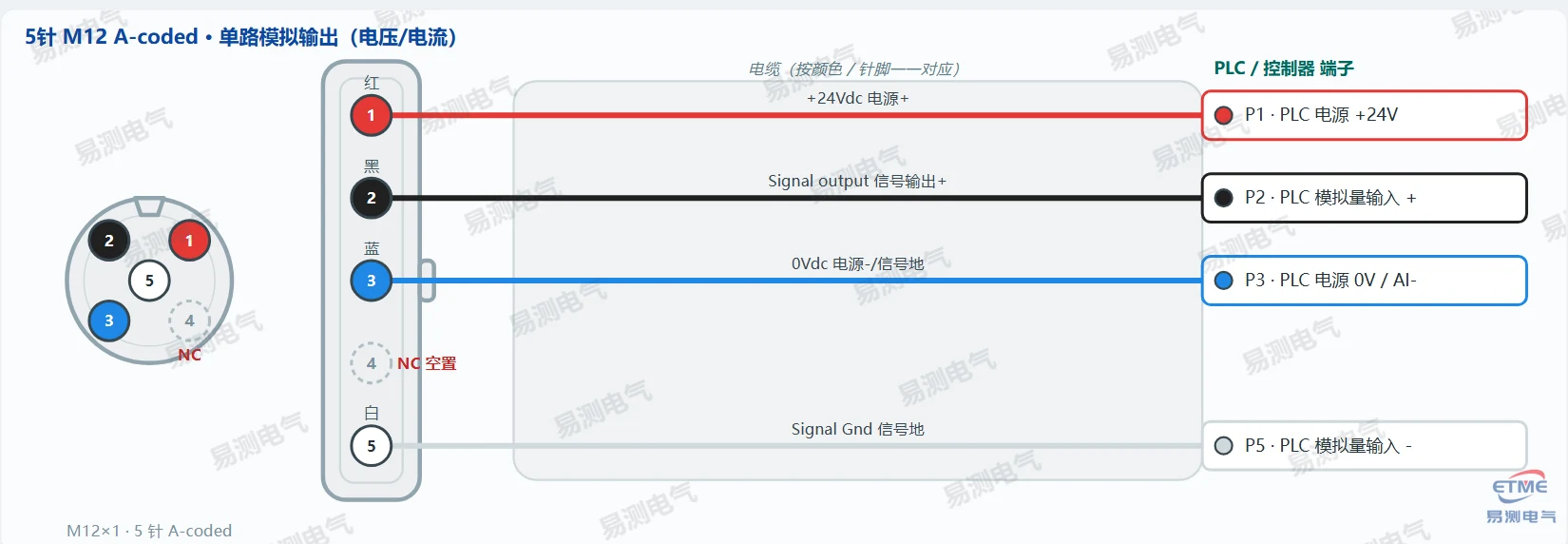
📌 The 5-pin M12 A-coded version carries a single analogue output: P1 = +24 V, P2 = signal output (0-10 V or 4-20 mA depending on the order code), P3 = 0 V, P5 = signal ground; P4 is left open. Wire colours per Germanjet 2024 Catalog p.103 / p.14.
▸ Start/Stop digital output (DIN 43650)
| Pin | Function | To controller |
|---|---|---|
| P1 | +24 Vdc supply + | PLC supply +24 V |
| P2 | START | PLC digital input Start |
| P3 | STOP | PLC digital input Stop |
| P4 | 0 Vdc supply minus | PLC supply 0 V |
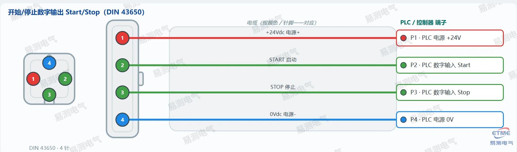
📌 Start/Stop is a pulse-counting interface; the PLC must provide the counter/timer input.
Series 17 magnetostrictive displacement sensor wiring (in-cylinder hydraulic · voltage / current / Start-Stop)
Built for hydraulic cylinders: the pressure-rated tube and hex flange are 100% stainless steel, electronics rated IP67. Besides the standard oil-proof 4-pin plug (DIN 43650), optional 5-pin M12 A-coded, D60 6-pin M16 and S32/S15 8-pin connectors are available — check the order code.
▸ Analogue voltage output 0-10 V / 10-0 V (DIN 43650)
| Pin | Function | To controller |
|---|---|---|
| P1 | +24 Vdc supply + | PLC supply +24 V |
| P2 | 10-0 V output + | PLC analogue input + (reverse direction) |
| P3 | 0-10 V output + | PLC analogue input + (forward direction) |
| P4 | 0 Vdc signal minus / supply minus | PLC analogue input - and supply 0 V |
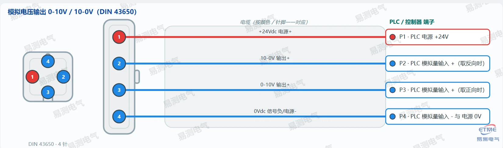
📌 Note: the negative (-) analogue input of the controller may only go to the sensor 0 V (P4), never to machine 0 V or earth. Dual output: P3 = 0-10 V (forward), P2 = 10-0 V (reverse), sharing P4 as negative / supply ground.
▸ Analogue current output 4-20 mA / 0-20 mA (DIN 43650)
| Pin | Function | To controller |
|---|---|---|
| P1 | +24 Vdc supply + | PLC supply +24 V |
| P2 | 4-20 mA output + | PLC analogue input + |
| P3 | Signal - , 4-20 mA output - | PLC analogue input - and supply 0 V |
| P4 | 0 Vdc supply minus | PLC supply 0 V |
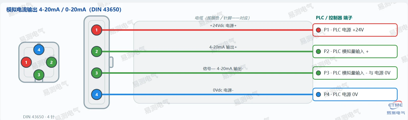
📌 4-20 mA is an active four-wire output (supply and signal fully separate): P1 = +24 V, P2 = 4-20 mA output +, P3 = signal - 4-20 mA output -, P4 = supply 0 V. P3 and P4 are not linked inside the sensor — all four conductors are used. At the PLC, P3 goes to analogue input AI- and P4 to supply 0 V; both must be wired, neither may float.
▸ 5-pin M12 A-coded · single analogue output (voltage or current)
| Pin | Function | To controller |
|---|---|---|
| P1 | +24 Vdc supply + | PLC supply +24 V |
| P2 | Signal output + | PLC analogue input + |
| P3 | 0 Vdc supply minus / signal ground | PLC supply 0 V / AI- |
| P4 | Not connected / N.C. | |
| P5 | Signal ground | PLC analogue input - |
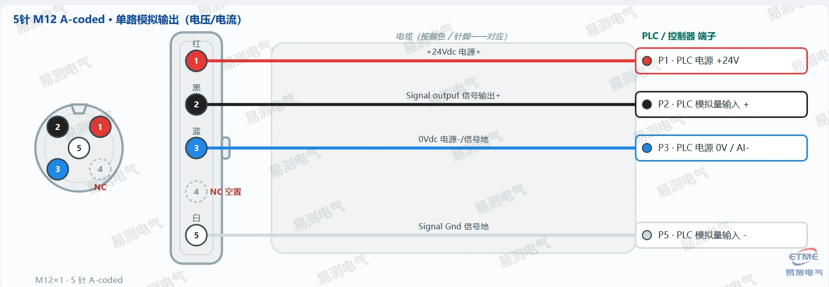
📌 The 5-pin M12 A-coded version carries a single analogue output: P1 = +24 V, P2 = signal output (0-10 V or 4-20 mA depending on the order code), P3 = 0 V, P5 = signal ground; P4 is left open. Wire colours per Germanjet 2024 Catalog p.102 / p.22.
▸ Start/Stop digital output (DIN 43650)
| Pin | Function | To controller |
|---|---|---|
| P1 | +24 Vdc supply + | PLC supply +24 V |
| P2 | START | PLC digital input Start |
| P3 | STOP | PLC digital input Stop |
| P4 | 0 Vdc supply minus | PLC supply 0 V |
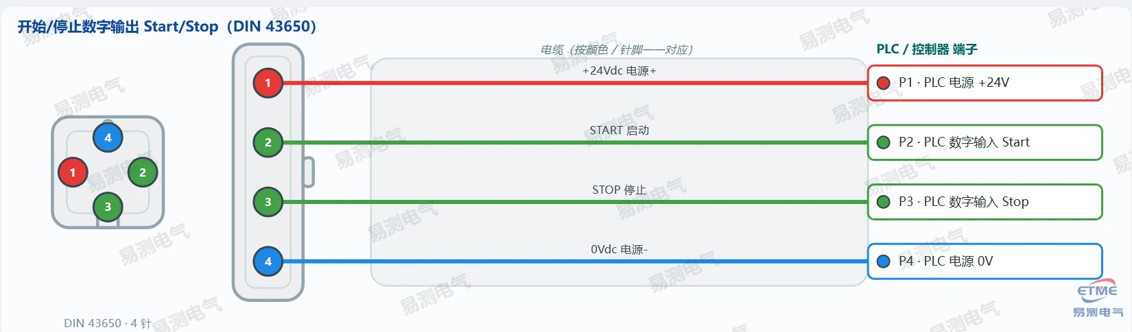
📌 Start/Stop is a pulse-counting interface; the PLC must provide the counter/timer input.
Series 13 magnetostrictive displacement sensor wiring (mobile hydraulic)
Designed for mobile hydraulics: pressure-rated stainless steel tube, IP68/IP69K protection, for construction machinery cylinders. Outputs are analogue voltage/current (4-pin M12 A-coded) or CANopen / SAE J1939 (5-pin M12 A-coded).
▸ Analogue voltage/current output (N_E pin-out 2-3-4)
| Pin | Function | To controller |
|---|---|---|
| P1 | Not connected / N.C. | |
| P2 | 12/24 Vdc supply + | PLC / vehicle supply + |
| P3 | 0 Vdc supply ground | PLC / vehicle supply 0 V |
| P4 | Output signal | PLC analogue input + |
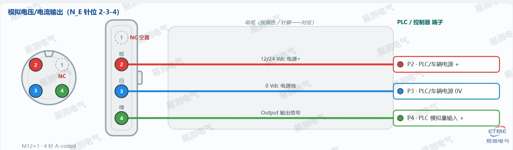
📌 N_E wiring: P2 = supply +, P3 = 0 V, P4 = signal output; P1 left open. This suits a single-ended voltage or current output — the range follows the order code (e.g. 015 = 0.5-10 V, 101 = 4-20 mA).
▸ Analogue voltage/current output (N_G pin-out 1-3-4)
| Pin | Function | To controller |
|---|---|---|
| P1 | 12/24 Vdc supply + | PLC / vehicle supply + |
| P2 | Not connected / N.C. | |
| P3 | 0 Vdc supply ground | PLC / vehicle supply 0 V |
| P4 | Output signal | PLC analogue input + |
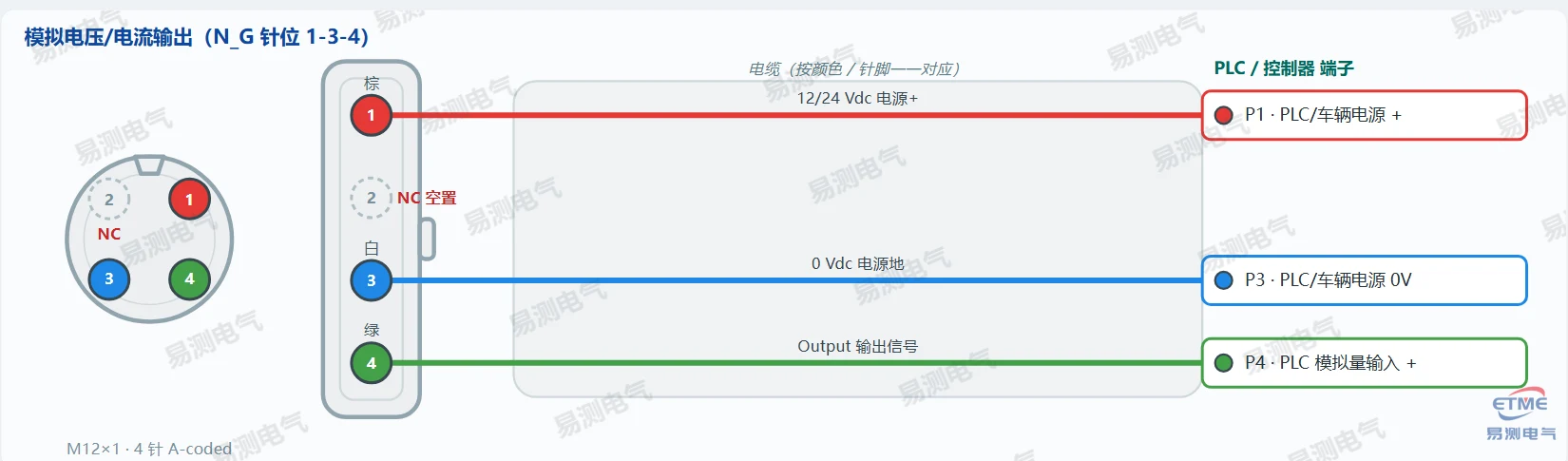
📌 N_G wiring: P1 = supply +, P3 = 0 V, P4 = signal output; P2 left open.
▸ Analogue voltage/current output (N_H pin-out 1-2-3)
| Pin | Function | To controller |
|---|---|---|
| P1 | 12/24 Vdc supply + | PLC / vehicle supply + |
| P2 | Output signal | PLC analogue input + |
| P3 | 0 Vdc supply ground | PLC / vehicle supply 0 V |
| P4 | Not connected / N.C. |
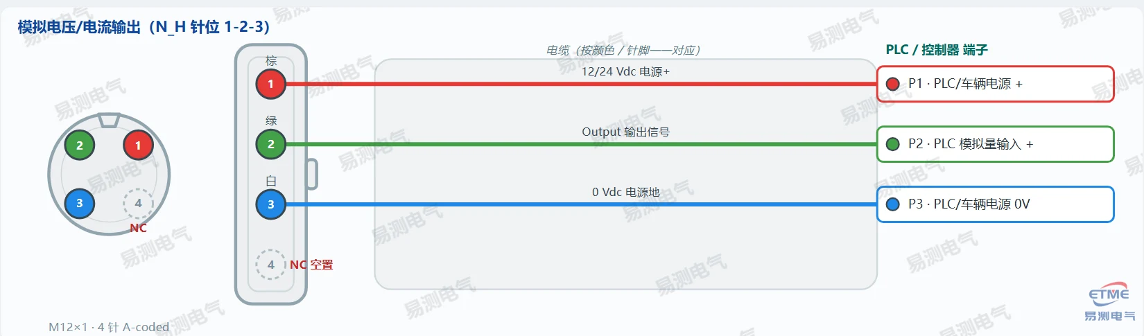
📌 N_H wiring: P1 = supply +, P2 = signal output, P3 = 0 V; P4 left open.
▸ CANopen / SAE J1939 (N_F pin-out 2-3-4-5)
| Pin | Function | To controller |
|---|---|---|
| P1 | Not connected / N.C. | |
| P2 | 12/24 Vdc supply + | CAN module supply + |
| P3 | 0 Vdc supply ground | CAN module supply 0 V |
| P4 | CAN High | CAN_H |
| P5 | CAN Low | CAN_L |
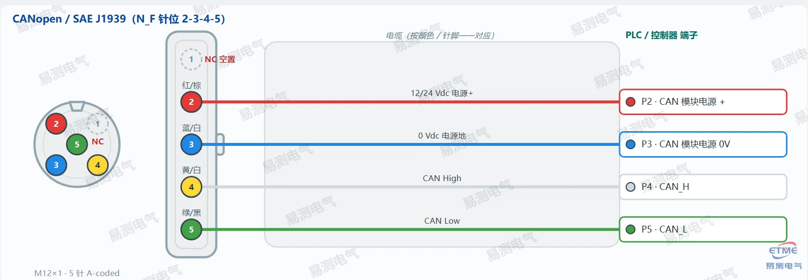
📌 N_F wiring: P2 = supply +, P3 = 0 V, P4 = CAN_H, P5 = CAN_L; P1 left open. Supports CANopen (CiA) and SAE J1939, baud rate configurable.
Series 16 magnetostrictive displacement sensor wiring (in-cylinder 16H / 16C)
For in-cylinder mounting (16H hydraulic in-cylinder / 16C miniature in-cylinder), with analogue and SSI outputs. Analogue uses the D60 (6-pin M16) connector; SSI synchronous serial output uses D70 (7-pin M16) or S32 (8-pin M16), or the R02/H02/T02/W02 direct cable options.
▸ Analogue voltage/current output (D60 six-pin)
| Pin | Function | To controller |
|---|---|---|
| P1 | 0-10 V output (forward) | PLC analogue input + |
| P2 | DC Gnd supply ground | PLC supply 0 V |
| P3 | 10-0 V output (reverse) | PLC analogue input - |
| P4 | Not connected / N.C. | |
| P5 | +24 Vdc supply + | PLC supply +24 V |
| P6 | 0 Vdc supply minus | PLC supply 0 V |
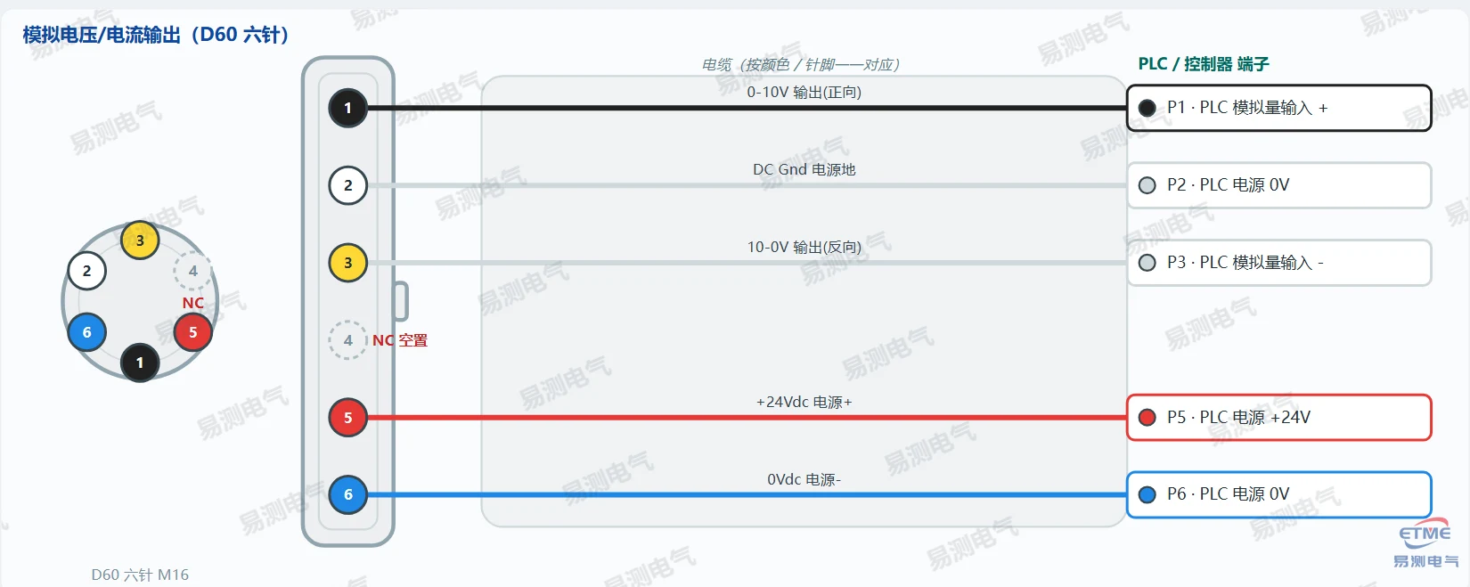
📌 Analogue (standard D60 wire colours: black = P1 0-10 V, white = P2 Gnd, yellow = P3 10-0 V, green = P4 N.C. leave open, red = P5 +24 V, blue = P6 0 V). For single-channel output only P1/P2/P5/P6 need wiring (P3/P4 may stay open); for dual output wire all of them. Order codes: 001 = 0-10 V, 011 = 10-0 V, 101 = 4-20 mA, 111 = 20-4 mA.
▸ SSI synchronous serial output (D70 seven-pin)
| Pin | Function | To controller |
|---|---|---|
| P1 | Data- | SSI Data - |
| P2 | Data+ | SSI Data + |
| P3 | Clock+ | SSI Clock + |
| P4 | Clock- | SSI Clock - |
| P5 | +24 Vdc supply + | SSI module +24 V |
| P6 | 0 Vdc supply minus | SSI module 0 V |
| P7 | Not connected / N.C. |
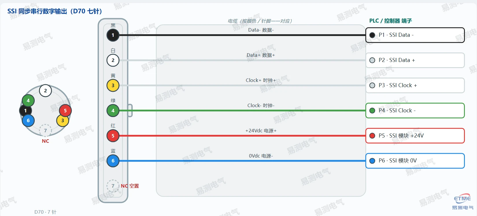
📌 SSI (D70 seven-pin, looking at the sensor pins): P1 black = Data-, P2 white = Data+, P3 yellow = Clock+, P4 green = Clock-, P5 red = +24 V, P6 blue = 0 V, P7 left open. Gray code or binary selectable.
▸ SSI synchronous serial output (S32 eight-pin)
| Pin | Function | To controller |
|---|---|---|
| P1 | Clock+ | SSI Clock + |
| P2 | Data+ | SSI Data + |
| P3 | Clock- | SSI Clock - |
| P4 | Not connected / N.C. | |
| P5 | Data- | SSI Data - |
| P6 | 0 Vdc supply minus | SSI module 0 V |
| P7 | +24 Vdc supply + | SSI module +24 V |
| P8 | Not connected / N.C. |
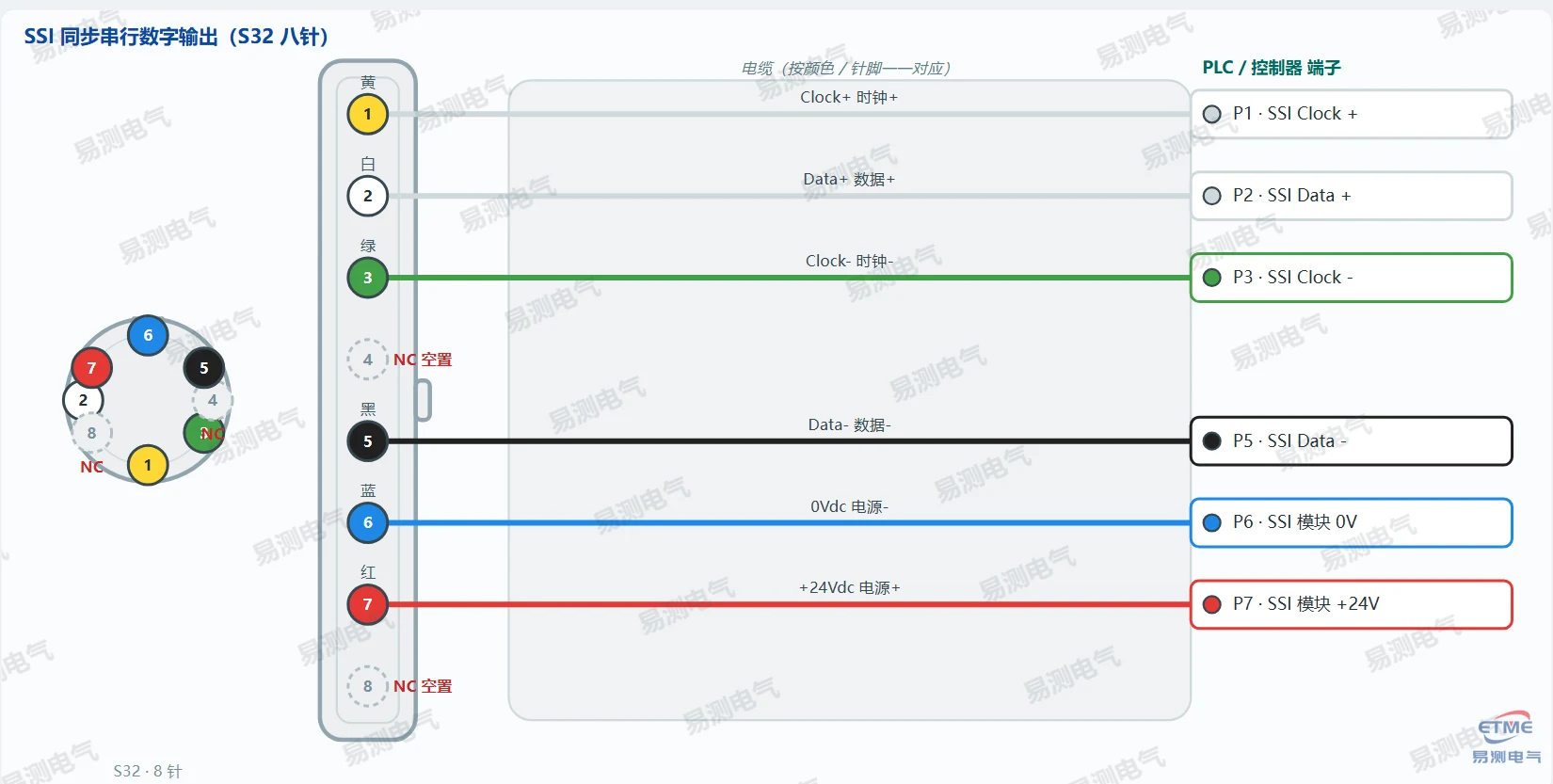
📌 SSI (S32 eight-pin, looking at the sensor pins): P1 yellow = Clock+, P2 white = Data+, P3 green = Clock-, P5 black = Data-, P6 blue = 0 V, P7 red = +24 V; P4/P8 left open. Wire colours per Germanjet 2024 Catalog p.107 (S32 SSI #24).
Series 12 magnetostrictive displacement sensor wiring (wall-thickness control servo cylinders)
Designed for wall-thickness control servo cylinders, with analogue voltage, Start/Stop and CANopen outputs. Analogue and digital versions use a 4-pin connector; the CANopen version uses an M12x1 IP69K connector.
▸ Analogue voltage output 0-10 V
| Pin | Function | To controller |
|---|---|---|
| P1 | +24 Vdc supply + | PLC supply +24 V |
| P2 | 10-0 V output + | PLC analogue input + (reverse direction) |
| P3 | 0-10 V output + | PLC analogue input + (forward direction) |
| P4 | 0 Vdc signal minus / supply minus | PLC analogue input - and supply 0 V |
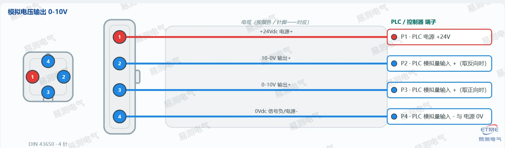
📌 Order codes: 00 = 0-10 V, 01 = 10-0 V, 10 = 4-20 mA, 11 = 20-4 mA, etc. Dual output: P3 = 0-10 V (forward), P2 = 10-0 V (reverse), sharing P4 as negative / supply ground.
▸ Start/Stop digital output
| Pin | Function | To controller |
|---|---|---|
| P1 | +24 Vdc supply + | PLC supply +24 V |
| P2 | START | PLC digital input Start |
| P3 | STOP | PLC digital input Stop |
| P4 | 0 Vdc supply minus | PLC supply 0 V |
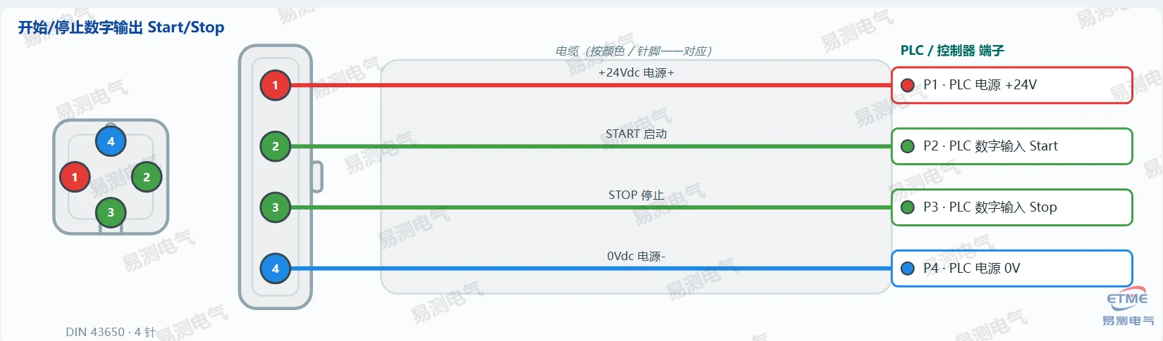
📌 Start/Stop pulse-counting interface.
▸ CANopen digital output (M12x1 IP69K)
| Pin | Function | To controller |
|---|---|---|
| P1 | +24 Vdc supply + | CANopen module +24 V |
| P2 | CAN(-) | CAN_L |
| P3 | CAN(+) | CAN_H |
| P4 | 0 Vdc supply minus | CANopen module 0 V |
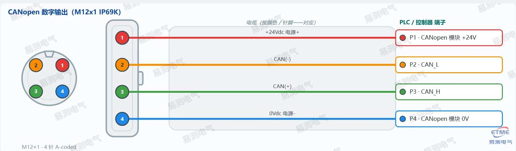
📌 Supports direct CANopen or CAN J1939, baud rate up to 1000 kBit/s.
Series 19 magnetostrictive displacement sensor wiring (intelligent digital · D60 six-pin M16 connector)
Series 19 is the intelligent digital family, offering analogue, Start/Stop, CANbus, Profibus-DP and EtherCAT/Profinet interfaces. Analogue and Start/Stop versions mostly use the D60 six-pin M16 connector (or the R02/H02/T02 direct cable); fieldbus versions (CANbus, Profibus-DP, EtherCAT, Profinet) in practice use a dedicated M12/M8 combination connector — see “Fieldbus connector notes” below. The D60 wire-colour table applies to the D60 version of analogue, start-stop and fieldbus units.
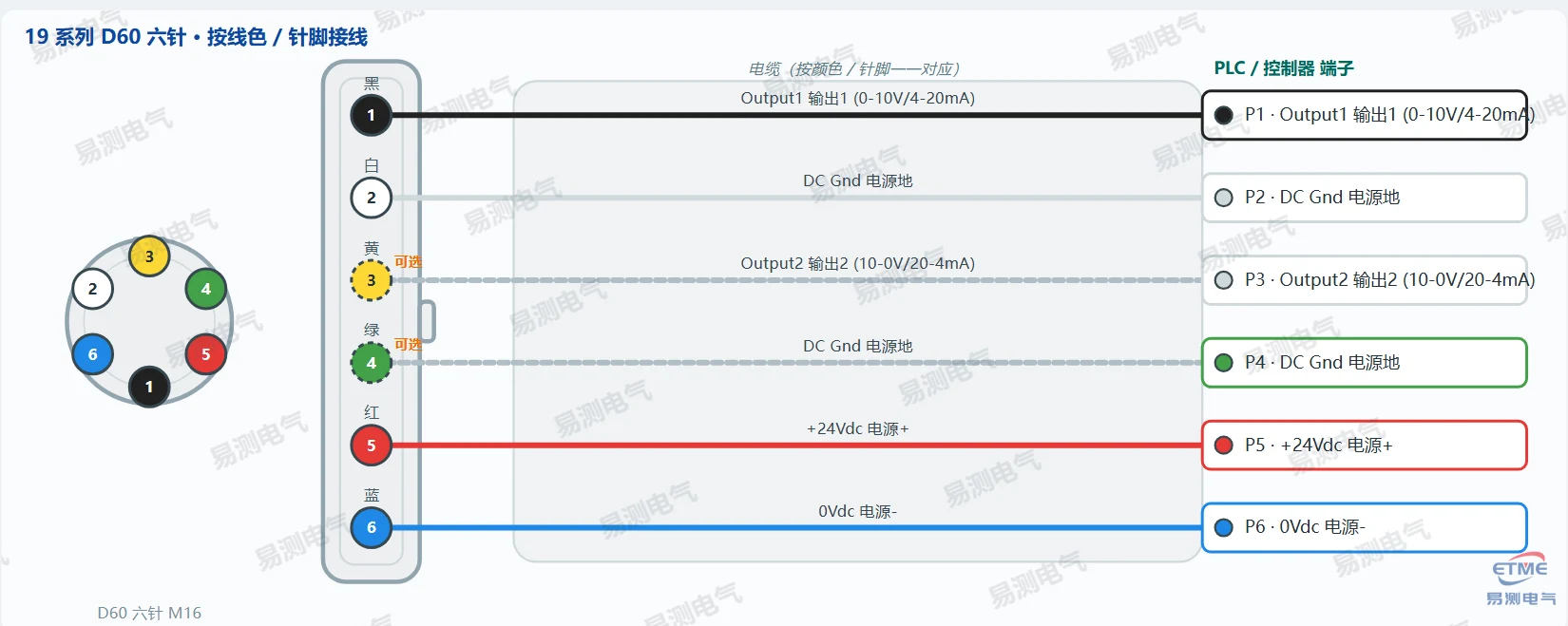
📌 Standard D60 wire colours (looking at the sensor pins): P1 black = Output1, P2 white = DC Gnd, P3 yellow = Output2, P4 green = DC Gnd, P5 red = +24 Vdc, P6 blue = 0 Vdc. The screen goes to the shell and is earthed at the controller end. On a single analogue channel, P3/P4 (Output2 and its ground) may be left open — marked “optional” in the diagram; with dual output all pins must be wired.
| Interface model | Output1 (P1 black) | Output2 (P3 yellow) | Supply |
|---|---|---|---|
| Analogue voltage/current 190 / 191 | Output1 (0-10 V / 4-20 mA) | Output2 (10-0 V / 20-4 mA) | P5 red +24 V / P6 blue 0 V |
| Start/Stop 193 | Start/Stop start · stop | Stop/Start stop · start | P5 red +24 V / P6 blue 0 V |
| CANbus 194 | CAN_H / CAN_L | CAN_L / CAN_H | P5 red +24 V / P6 blue 0 V |
| Profibus-DP 195 | Profibus A / B | Profibus B / A | P5 red +24 V / P6 blue 0 V |
| EtherCAT 197 / 198 | EtherCAT signal | EtherCAT signal | P5 red +24 V / P6 blue 0 V |
Series 19 fieldbus connector notes (M12 / M8)
Compiled from the Accessories pages of the Germanjet 2024 Catalog. Fieldbus versions normally split “bus in/out” and “24 V supply” across two connectors: one M12 for the bus, one M8 for power. Choose by the connector code in the order code; the actual pin assignment on the delivery label always takes precedence.
| Interface | Order code example | Bus Input | Bus Output | 24 V Power |
|---|---|---|---|---|
| CANbus | 194 D54 / S94 / D34 | 5p M12 A female | 5p M12 A male (D54 / S94) | 4p M8 female (D54) |
| Profibus-DP | 195 D53 / S13 / D63 | 5p M12 B female / 6p D60 female | 5p M12 B male / 6p D60 male | 4p / 3p M8 female (D53 / S13) |
| EtherCAT | 197 Series | 4p M12 D male | 4p M12 D male | 4p M8 female |
| Profinet | 199 D56 / D58 | 4p M12 D male | 4p M12 D male | 4p M8 female (D56) / 4p M12 A female (D58) |
📌 Wiring notes: on a fieldbus version, first check how many connectors the sensor body carries. If there is only one D60 six-pin, wire to the D60 table above. If it is an M12 + M8 combination, the M12 takes the bus and the M8 takes +24 V / 0 V. Profibus uses M12 B-coded, CANbus uses M12 A-coded, EtherCAT/Profinet use M12 D-coded — never mix them up.
7-pin D70 plug magnetostrictive displacement sensor wiring (SSI synchronous serial 192 etc.)
Some models (such as SSI 192) use a 7-pin D70 male plug. Pin 7 is “not connected / NC” — it is left open at the factory and does not need wiring on site. The remaining six pins carry the differential clock/data pair and the supply, with fixed wire colours as below.
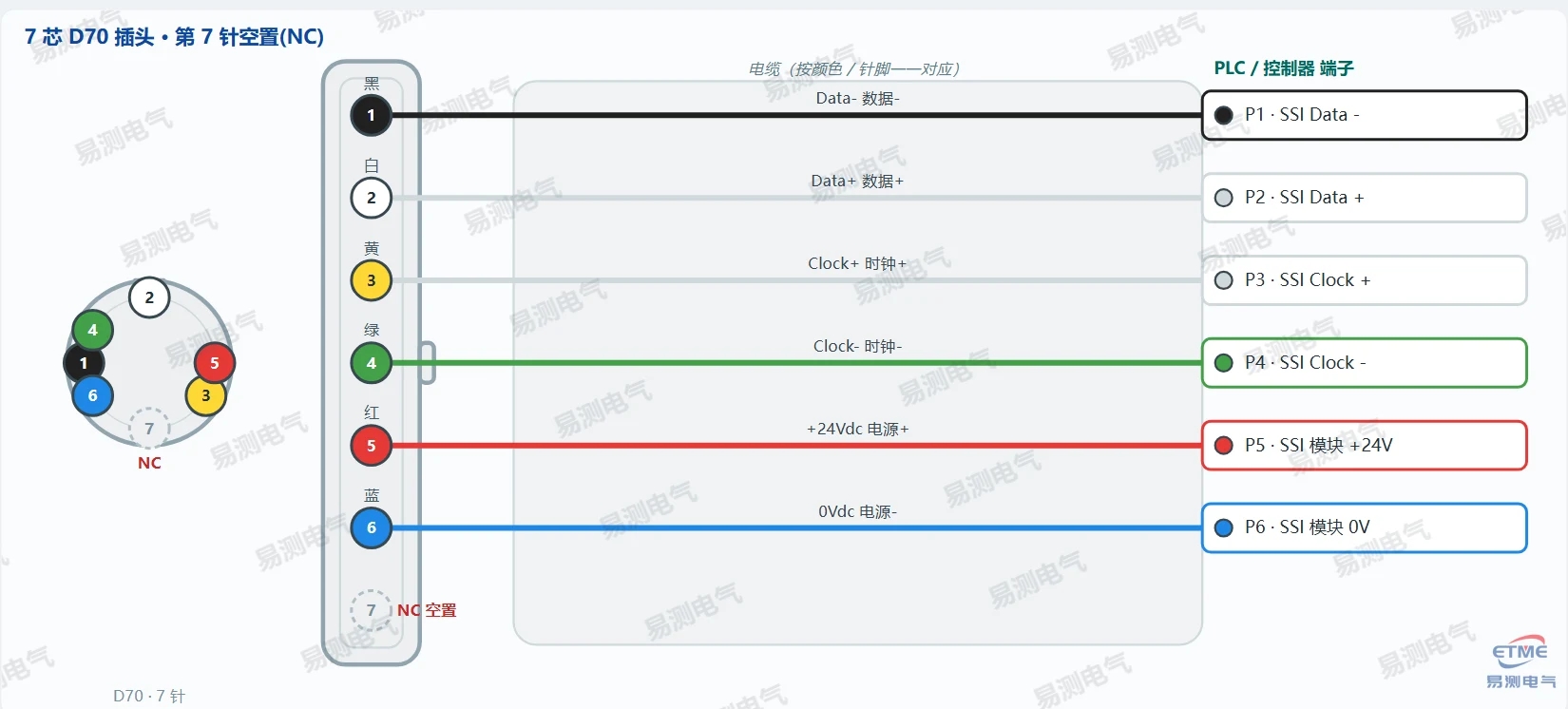
📌 Wiring notes: P1 black = Data-, P2 white = Data+, P3 yellow = Clock+, P4 green = Clock-, P5 red = +24 V, P6 blue = 0 V; P7 is not connected — leave it open (the grey dashed NC pin in the diagram). The screen goes to the shell and is earthed at the controller end.
📋 Quick reference table: magnetostrictive displacement sensor pin functions
The table below summarises the pin functions from every magnetostrictive displacement sensor wiring diagram above, so a site engineer can check the supply, signal and bus definition of P1–P7 at a glance and avoid a miswiring.
| Series | Connector | P1 | P2 | P3 | P4 | (P5/P6) |
|---|---|---|---|---|---|---|
| 18 analogue voltage | 4-pin DIN 43650 | +24 V | 10-0 V | 0-10 V | 0 V | — |
| 18 analogue current | 4-pin DIN 43650 | +24 V | 4-20 mA output + | Signal - , 4-20 mA - | 0 V supply - | — |
| 18 single analogue | 5-pin M12 A | +24 V red | Output black | 0 V blue | N.C. | P5 signal ground white |
| 18 Start/Stop | 4-pin DIN 43650 | +24 V | START | STOP | 0 V | — |
| 17 analogue voltage | 4-pin DIN 43650 | +24 V | 10-0 V | 0-10 V | 0 V | — |
| 17 analogue current | 4-pin DIN 43650 | +24 V | 4-20 mA output + | Signal - , 4-20 mA - | 0 V supply - | — |
| 17 single analogue | 5-pin M12 A | +24 V red | Output black | 0 V blue | N.C. | P5 signal ground white |
| 17 Start/Stop | 4-pin DIN 43650 | +24 V | START | STOP | 0 V | — |
| 16 analogue voltage/current | D60 six-pin M16 | 0-10 V (black) | DC Gnd (white) | 10-0 V (yellow) | N.C. (green) | +24 V red / 0 V blue |
| 16 SSI (D70 7-pin) | D70 7-pin M16 | Data- (black) | Data+ (white) | Clock+ (yellow) | Clock- (green) | P5 red +24 V / P6 blue 0 V / P7 NC |
| 16 SSI (S32 8-pin) | S32 8-pin M16 | Clock+ (yellow) | Data+ (white) | Clock- (green) | N.C. | P5 black Data- / P6 blue 0 V / P7 red +24 V / P8 NC |
| 13 analogue N_E | 4-pin M12 A | N.C. | +V brown | 0 V white | Output green | — |
| 13 analogue N_G | 4-pin M12 A | +V brown | N.C. | 0 V white | Output green | — |
| 13 analogue N_H | 4-pin M12 A | +V brown | Output green | 0 V white | N.C. | — |
| 13 CANopen N_F | 5-pin M12 A | N.C. | +V red / brown | 0 V blue / white | CAN_H yellow / white | P5 CAN_L green / black |
| 12 analogue voltage | 4-pin | +24 V | 10-0 V | 0-10 V | 0 V | — |
| 12 Start/Stop | 4-pin | +24 V | START | STOP | 0 V | — |
| 12 CANopen | M12x1 IP69K | +24 V | CAN(-) | CAN(+) | 0 V | — |
| 19 all interfaces | D60 six-pin M16 | Output1 (black) | DC Gnd (white) | Output2 (yellow) | DC Gnd (green) | +24 V red / 0 V blue |
| 19 fieldbus | M12 / M8 combination | — | — | — | — | see the fieldbus table |
| 19 SSI 192 | 7-pin D70 | Data- (black) | Data+ (white) | Clock+ (yellow) | Clock- (green) | +24 V red / 0 V blue, P7 open |
Note: cable colours for Series 17/18/12 follow the ordered model; always wire by pin number (P1–P4). Series 19 wire colours are fixed as listed.
Source: Germanjet Magnetostrictive Displacement Sensors V3.1 product catalogue and the Germanjet English catalogue. This guide is a site wiring reference; the product label and factory documentation always take precedence.
Frequently Asked Questions
Q: Which table do I use for my sensor?
Match the series and the connector first: 18 external, 17 / 16 in-cylinder, 13 mobile, 12 servo cylinder, 19 digital (D60 / M12), 7-pin D70 for SSI. The wrong series table means wrong pins.
Q: Can I join signal minus to the supply 0 V?
No. Analogue outputs are four-wire: the supply pair and the signal pair are fully separate. Joining them creates a ground loop and shifts the reading.
Related Products
Related Applications
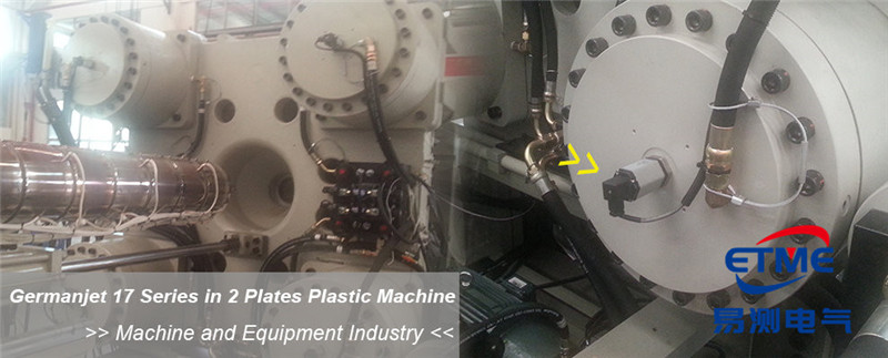
Series 17 Hydraulic Cylinder Integrated Magnetostrictive Displacement Sensor Application Cases
View Details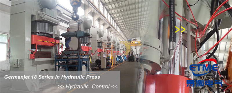
Series 18 Profile Magnetostrictive Displacement Sensor Application Cases
View Details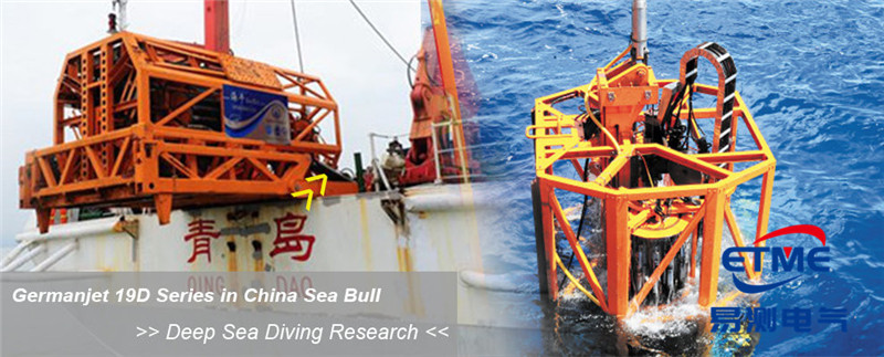
Series 19D Split-Type Process Displacement Sensor Application Cases
View Details