CANopen Displacement Sensor: EMCY, Node Start, PDO and SYNC Communication Examples
CANopen magnetostrictive displacement sensors report position over the bus, but the first day on site usually fails on one thing: which telegram does what. This article walks through the four frames you actually use on a Germanjet Series 19 CANopen displacement sensor — EMCY, node start, PDO and SYNC — and the order to send them in so the master and the sensor agree.
The four telegrams and their jobs
- EMCY (Emergency) — the sensor pushes an error frame when something is wrong inside (over-voltage, memory error, position fault). It is not a request; you read it to diagnose.
- NMT node start — the master puts the node into Operational state. Nothing is sent or received until the node is started.
- PDO (Process Data Object) — the actual position value. TPDO carries the position from sensor to master; RPDO writes to the sensor.
- SYNC — a bus-wide heartbeat. When SYNC is enabled, the sensor publishes its TPDO on every SYNC, which synchronises several sensors on the same bus.
Default COB-IDs and the frames you actually see
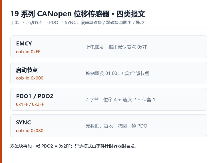
On power-up the sensor immediately sends one EMCY frame with COB-ID 0xFF — the "I am here" frame, which also reveals its default node address 0x7F, 127 in decimal. The master then sends the node start frame: COB-ID 0x000, two data bytes 01 00, where 01 means start and 00 means all nodes. Sending 01 7F starts node 0x7F alone.
Once started, the sensor answers with PDO1, COB-ID 0x1FF, seven data bytes: four bytes of position, two bytes of velocity and one reserved byte (00). Both values are sent LSB first — receiving 03 83 00 00 means the position is 0x00008303, or 33539 counts; at the 0.005 mm resolution that is 33539 × 0.005 = 167.695 mm.
This is where synchronous and asynchronous operation part company. In the synchronous connection the sensor answers every SYNC frame, COB-ID 0x080 (no data), with one PDO. The master sends node start once at initialisation and is driven by SYNC afterwards, so you decide how many frames are read per cycle and the rhythm is fully under control. In the asynchronous connection the sensor enters Operational state after node start and then publishes its PDO on its own timer — no SYNC at all. How fast it publishes is set by the CAN event timer, which is covered in a separate article.
With two magnet rings the principle is the same, just one frame more. PDO1 stays at 0x1FF for the first ring and PDO2 uses 0x2FF for the second; each frame keeps the 4-byte position + 2-byte velocity + 1 reserved byte layout. Under SYNC one SYNC brings out both frames; asynchronously each ring's PDO follows its own event timer. Two positions from one sensor, carried in two separate frames.
Four details that are easy to miss on site
- The default node address is 0x7F. If several sensors share one bus, give each of them its own address first — do not leave them all answering on 0x7F.
- Node start is sent once, at initialisation. In synchronous mode the rest is driven by SYNC only; repeating node start every cycle is harmless but pointless.
- Confirm the resolution before converting counts to millimetres. The 0.005 mm used above is an example — the order code decides it, and the same raw value means a different position at a different resolution.
- The PDO already carries velocity as well as position. If the controller needs speed feedback it is in the same frame; no extra channel is required.
When one frame does not add up, work back from the COB-ID of the EMCY and PDO frames to the node address — that check usually finds it straight away.
Start-up order that works
- Power the sensor and let it boot (roughly 0.5 s).
- Send NMT start to the node — after this the sensor is online and answers SDO.
- Read the object dictionary over SDO to confirm node ID and baud match the master.
- Enable the TPDO you need (position, and optionally velocity) and map it to the correct COB-ID.
- If you use SYNC, enable the SYNC consumer and check the period on the master side.
- Watch the EMCY telegram for the first few minutes — most wiring mistakes surface there before the PLC logic sees them.
Full parameter changes — baud rate, node address and the CAN event timer — are covered step by step in changing CANopen parameters over SDO. If several sensors must share one bus node, see seven electronic rulers on one CANbus node.
Common first-run mistakes
- Node never started → sensor is silent even though the wiring is correct. Always send node start.
- COB-ID mismatch → position never arrives. Check the PDO mapping and the node ID on both sides.
- SYNC period shorter than the sensor cycle → duplicate or skipped frames. Keep the SYNC period longer than one measurement cycle.
- EMCY flooding → usually supply or shield, not the sensor. Fix the 24 V and the screen before touching the mapping.
Output choice is a selection-stage decision; see how to fix the output at selection if you are still deciding between CANopen, SSI and 4-20 mA.
Frequently Asked Questions
Q: The sensor is silent after wiring. What first?
Send the NMT node start to put the node in Operational state. A sensor that is powered but not started answers nothing even with correct wiring.
Q: EMCY frames are flooding. What do I check?
Supply stability and the shield first. EMCY flooding on first run is usually 24 V ripple or a bad screen, not the sensor.
Related Products
Related Applications
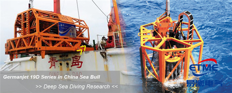
Series 19D Split-Type Process Displacement Sensor Application Cases
View Details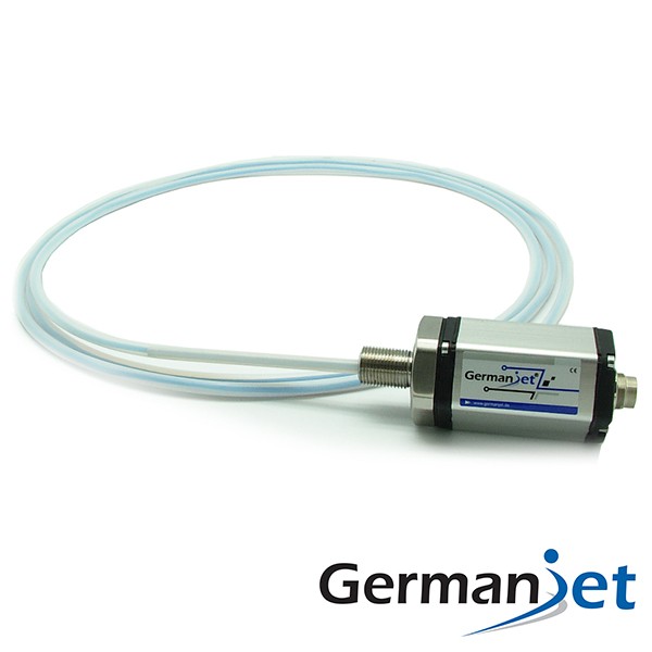
Series 19F Flexible Process Displacement Sensor Application Cases
View Details
Series 19H Cylinder-Integrated Process Displacement Sensor Application Cases
View Details