Displacement Sensor Selection: Stroke, Mounting, Output, Accuracy, Environment
Selecting a displacement sensor is a decision sequence, not a checklist. If you pick accuracy before stroke, or output before mounting, you often end up with a sensor that cannot physically fit. This article gives the five-step selection order, why the order matters, and a quick comparison table for Germanjet magnetostrictive sensors.
The five steps — the order is the decision order
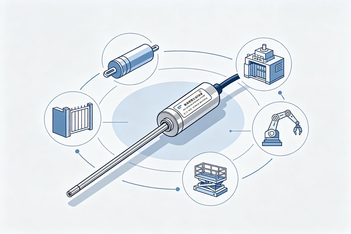
- Stroke — measure the real travel first, then add 10-20% margin with a mechanical buffer at each end. Stroke decides the rod length and the mounting space, so it comes first — and it is the decision that is hardest to change later.
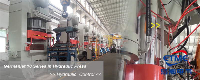
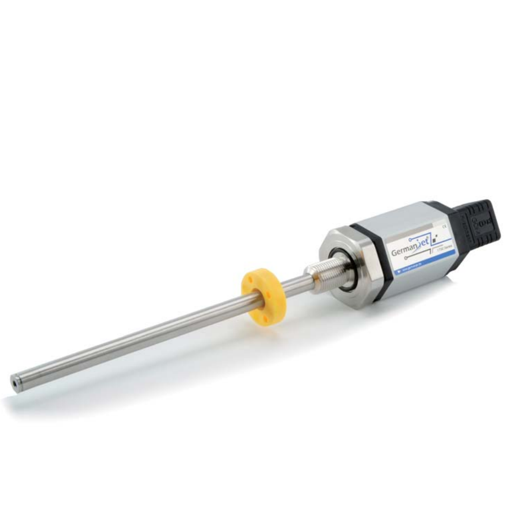
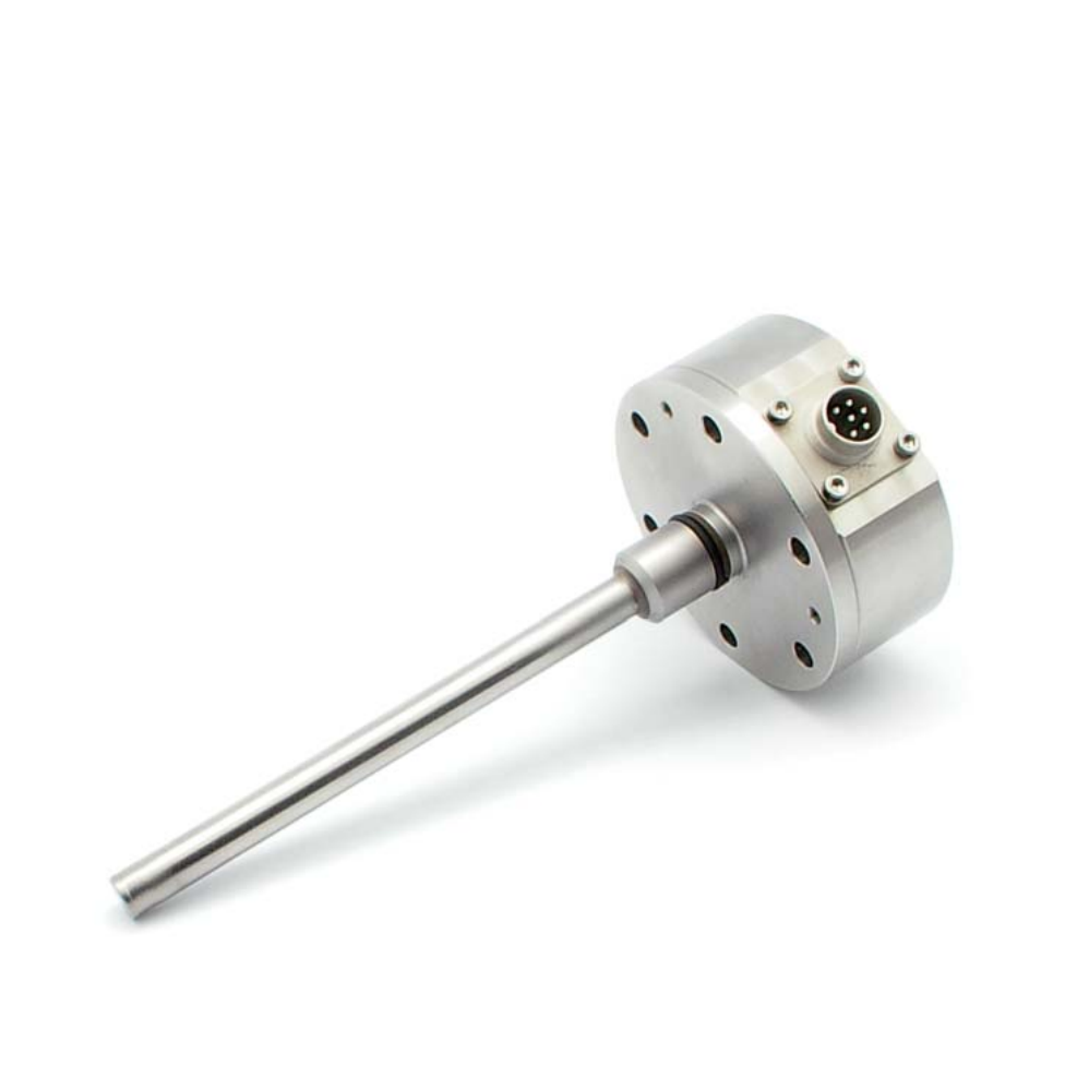
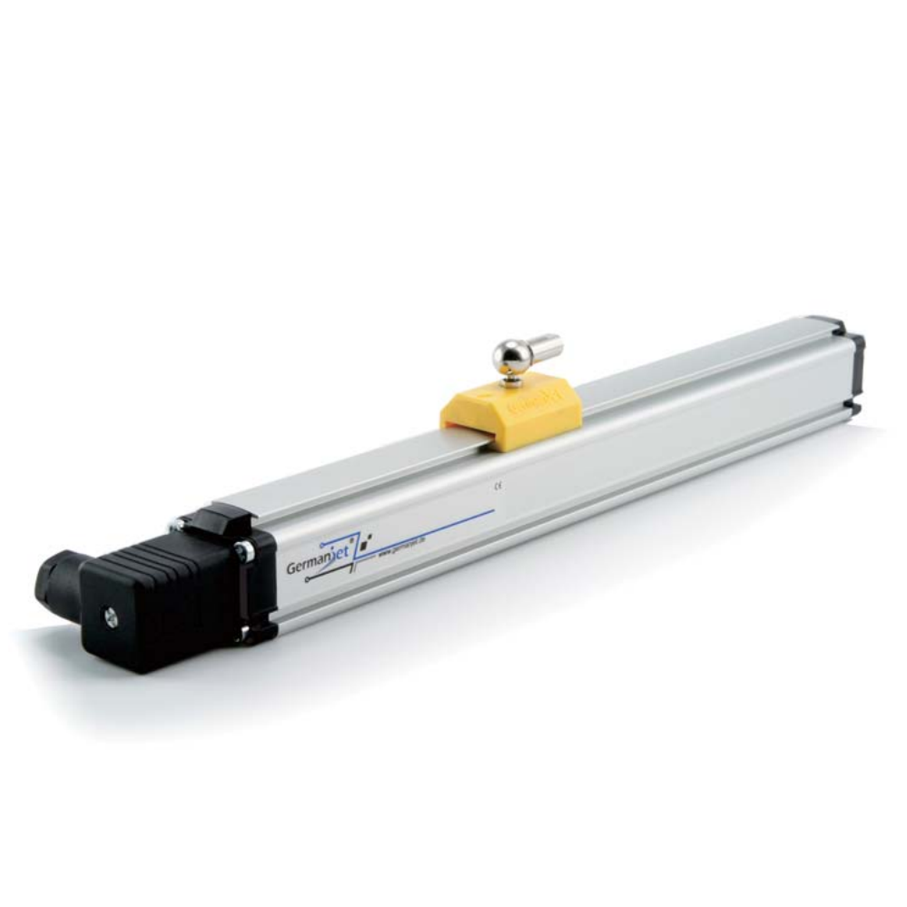
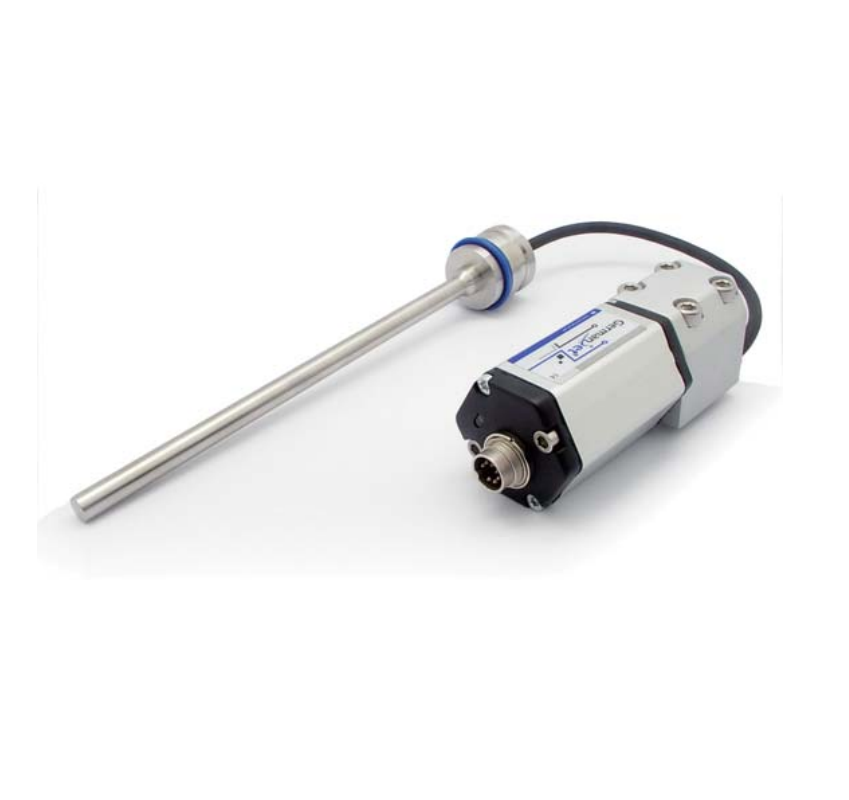
- Mounting — where does the sensor go? External: the rod runs parallel to the machine outside the cylinder, bracket-mounted, with the magnet ring linked to the moving part — the Germanjet 17 / 18 series, and the easiest route for a retrofit. In-cylinder: the rod goes inside the hydraulic cylinder body and the magnet ring sits on the piston in direct contact with the oil — the 16 / 19 series, for new cylinder builds. Level: the same sensor platform with a stainless float instead of the magnet ring, measuring liquid level.
- Output — what does the controller accept? Analogue: 4-20 mA / 0-10 V into a PLC analogue card — universal, cheap, good enough for most jobs. Start/Stop: a two-wire pulse interface into a dedicated counter module. Bus: SSI, CANopen, Profibus-DP, EtherCAT or Profinet into the PLC network — immune to interference and adjustable online. Decide this at selection; an output cannot be converted later.
- Accuracy — resolution runs from 0.005 mm to 0.05 mm, and repeatability follows the same grades. Higher is not automatically better: choose a fine resolution for closed-loop positioning, while a plain travel-switch decision is served by the standard grade. Do not pay for accuracy the job never uses.
- Environment — temperature range (ambient or high temperature), ingress protection (IP67 indoors, IP68 outdoors), whether the rod touches hydraulic oil, strong vibration, and whether the area is hazardous and needs an intrinsically safe version (Ex ia IIC T6). Each of these maps to a different housing and sealing grade.
Why the order cannot be shuffled
Stroke limits the rod; mounting limits the series; output limits the electronics; accuracy limits the grade. Choosing accuracy first usually picks a sensor that does not fit the mounting; choosing output first picks a series that lacks the stroke. Run the order top to bottom and each step narrows the list instead of expanding it.
Three things most people miss
- How the magnet ring moves. Reciprocating or rotating, and how fast, decides how the ring is fixed and whether the sensor responds quickly enough.
- Supply and signal format. Germanjet analogue sensors are four-wire with a 24 V supply — check that the machine has a supply available for the sensor as well as for the controller.
- Spare-part consistency. When replacing a sensor on an older machine, compare the stroke, output and mounting hole pitch of the original model first — do not go by brand alone.
Quick reference (Germanjet example)
| Need | Series to look at | Outputs |
|---|---|---|
| External, general purpose | 18 | 0-10 V, 4-20 mA, start-stop |
| Hydraulic in-cylinder | 16, 19 | analogue, CANopen, Profibus, SSI |
| Mobile hydraulics | 13 | analogue |
| Wall-thickness servo cylinders | 12 | 4-20 mA |
| Bus network (CANopen / Profibus) | 19 | CANopen, Profibus, EtherCAT, Profinet |
| Outdoor or washdown | sealed IP67 / IP68 range | analogue or bus, depending on the model |
| Hazardous area | intrinsically safe range | Ex ia IIC T6 |
The last step
Put the five answers into one sentence of requirement — for example "stroke 1000 mm, external mounting, 4-20 mA, 0.01 mm resolution, ambient workshop temperature" — and check it against the product pages. The model is fixed in minutes. When the duty is unclear, send the conditions to the factory and let them recommend from your five answers; it is far quicker than guessing from a parameter table.
Write the stroke, mounting, output, accuracy and environment into the enquiry together with the magnet ring form. A complete set of five answers prevents the classic back-and-forth: the sensor that arrives is the one that fits, speaks the right signal and survives the site.
After selection, follow installation and commissioning and the complete wiring reference.
Frequently Asked Questions
Q: Stroke first or accuracy first?
Stroke first. Stroke decides the rod length and the series; accuracy only narrows the grade. Picking accuracy first usually selects a sensor that does not fit.
Q: Can I change the output later?
No. An SSI output cannot be freely converted to 4-20 mA or a bus. Fix the output at selection, matching the controller input.
Related Products
Related Applications
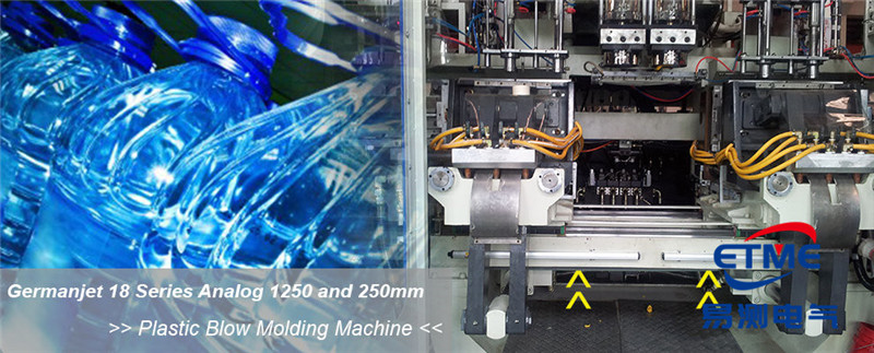
Series 12 General-Purpose Magnetostrictive Displacement Sensor Application Cases
View Details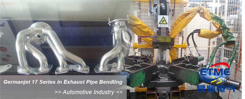
Series 16 Hydraulic Rod Magnetostrictive Displacement Sensor Application Cases
View Details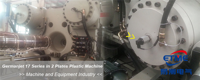
Series 17 Hydraulic Cylinder Integrated Magnetostrictive Displacement Sensor Application Cases
View Details