
Magnetostrictive Displacement Sensor Installation and Commissioning
Installing a magnetostrictive displacement sensor well is mostly preparation: choose the mounting form, fit the sensor cleanly, power it up and check three things, then set zero, span and direction. This article walks the whole commissioning sequence for external and in-cylinder mounting.
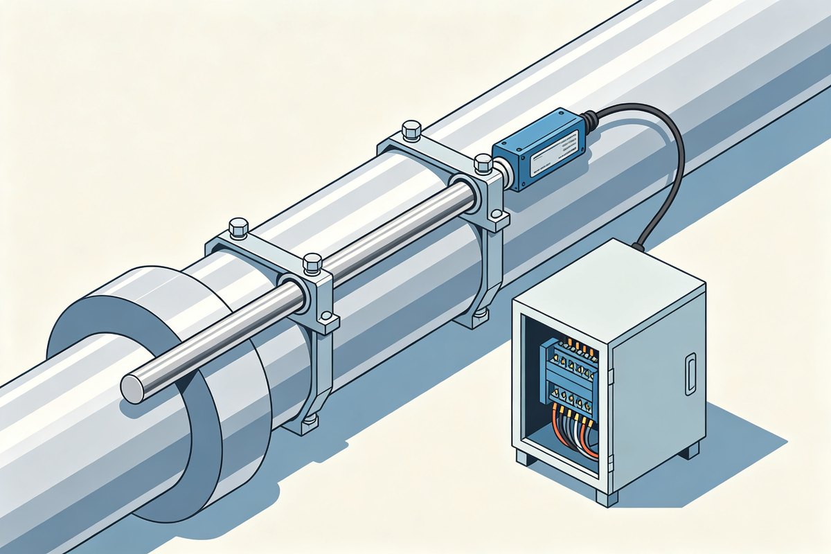
First choose the mounting form
- External (bracket) — the sensor body is fixed to the machine, the magnet ring rides on the moving part. Easy to retrofit, easy to adjust.
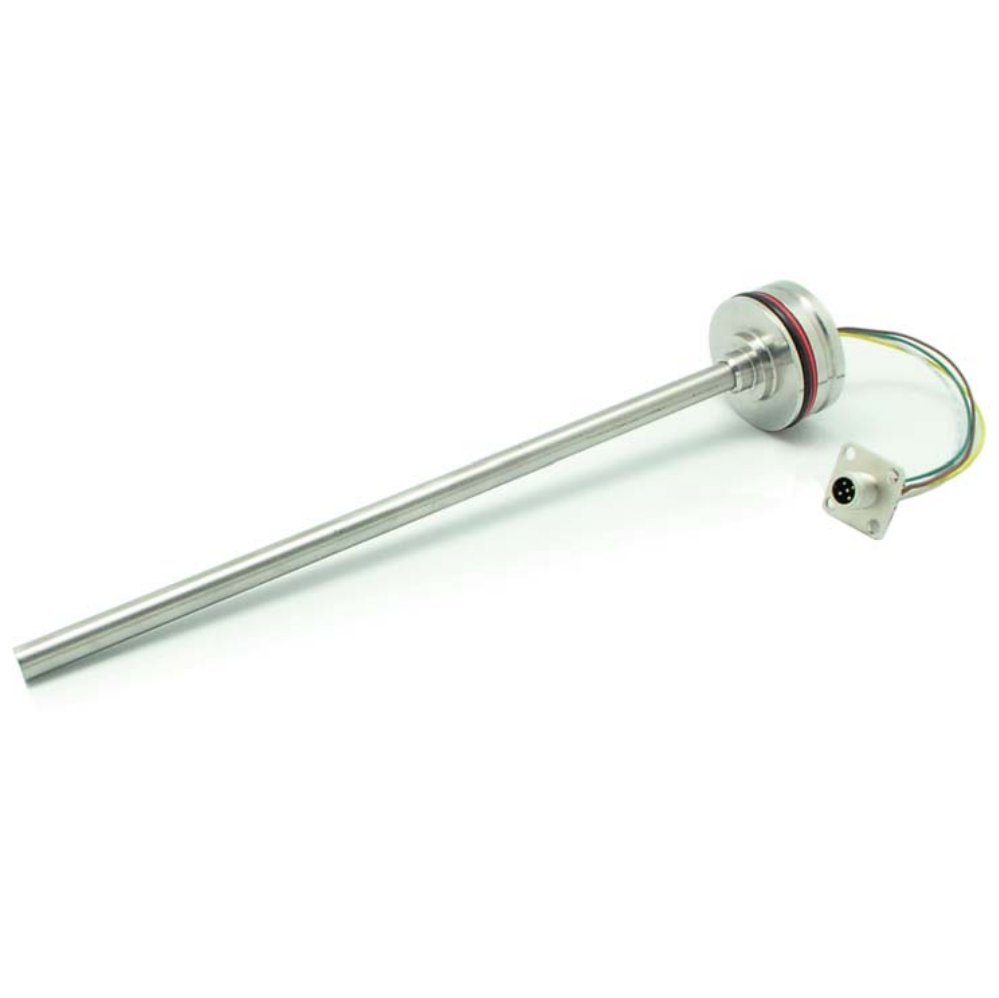
- In-cylinder — the rod goes through the cylinder head, the ring is on the piston. More robust, but the cylinder design must accept the rod and the mounting bore.
Installation steps (external example)
- Fix the bracket so the rod is straight and parallel to the travel axis — a tilted rod wears the guide and skews the reading.
- Fit the magnet ring so it travels freely over the whole stroke without touching the ends.
- Route the cable with a service loop, away from heat and moving parts.
- Wire per the series pin table and power up.
Power-on check (three looks)
- Look 1 — the position reading moves smoothly and continuously when you slide the ring by hand.
- Look 0 — before anything else, put a multimeter on +24 V and 0 V at the sensor: the supply must sit inside the rated range and must not move when other axes run.
- Look 2 — the reading has no dead band at the ends; the ring stays inside the calibrated range.
- Look 3 — the reading does not flicker at rest; flicker at rest is supply or shielding, not the sensor.
Setting the parameters
- Zero — put the machine at the reference position, set the reading to the reference value. For a 4-20 mA output that reference is 4 mA; for 0-10 V it is 0 V.
- Span — move to the far position and adjust so the reading matches the real travel. The far position is 20 mA, or 10 V on a voltage output.
- Direction — if the reading runs the wrong way, invert the counting direction instead of rewiring.
- Bus versions: set node ID, baud and PDO mapping in the configuration software, then save to EEPROM so the values survive power-off.
Usage points
- Keep the rod clean — ferrous dust on the rod distorts the reading locally.
- Never let the ring hit the mechanical ends; a hard stop bends the ring or the guide.
- Check the cable clamp regularly on machines with vibration.
- Where the temperature swings, repeat the zero and span check after a loaded run — the values move as the machine warms up.
Wiring tables for all series are in the complete wiring reference, and parameter writing over CANopen in changing CANopen parameters.
Frequently Asked Questions
Q: The reading flickers at rest. What is it?
Supply ripple or shielding, not the sensor. Stabilise the 24 V and check the screen earthing before touching the sensor.
Q: Do I need to rewire to reverse the direction?
No. Invert the counting direction in the settings; rewiring is unnecessary and risks a wrong pin.
Related Products
Related Applications
General Applications
Multi-Industry Application Cases for Magnetostrictive Displacement Sensors
View Details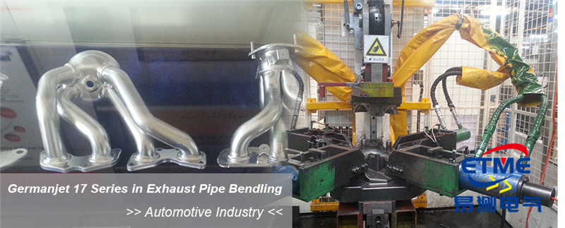
Hydraulic Rod / Profile
Series 16 Hydraulic Rod Magnetostrictive Displacement Sensor Application Cases
View Details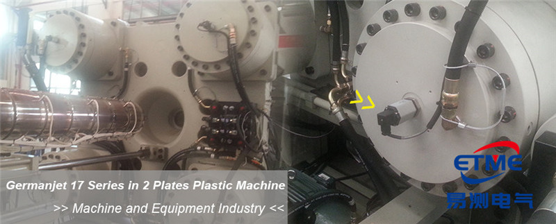
Injection Molding / Hydraulic Cylinder Integration
Series 17 Hydraulic Cylinder Integrated Magnetostrictive Displacement Sensor Application Cases
View Details
Profile / Built-in