
Magnetostrictive Displacement Sensor Series 194: CANopen DSP406 in Practice
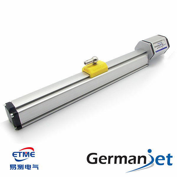
Series 194 is Germanjet’s CANopen fieldbus magnetostrictive displacement sensor, following the CiA DSP406 encoder profile. Against a point-to-point interface, its core value is several axes on one cable: one twisted-pair shielded cable strings several sensors and greatly reduces the harness; it also supports online parameter read/write and fault diagnostics. CANopen is most widely used on mobile machinery, hydraulic equipment and small-to-medium multi-axis systems, because mobile controllers almost all natively support CAN and the bus itself is tolerant of the electrical environment.
What the DSP406 profile solves
The CANopen base specification (DS301) defines only the communication mechanism, not “which object the position value sits in”. If each manufacturer defines its own, the master must write a parser for every brand. DSP406 is the device profile for encoders / position sensors; it unifies the object-dictionary location and data type of position value, resolution, preset, counting direction and other parameters.
The practical meaning is direct: the master is configured to DSP406, so when the sensor brand or model is changed the mapping need not be rewritten. Engineering should confirm three things — the sensor supports DSP406, the master / higher-level software also parses DSP406, and the EDS file version matches the firmware on the device. The CANopen object dictionary and the division of PDO/SDO are in CANopen introduction: object dictionary and the division of PDO/SDO.
Division of PDO and SDO
| Item | PDO (process data object) | SDO (service data object) |
|---|---|---|
| Use | Cyclic / event transfer of real-time position | Read/write parameters, configure the object dictionary |
| Message overhead | Small; data sit directly in the message | Large; request–response handshake required |
| Real-time performance | High | Low |
| Typical timing | Used continuously in operation | Used in configuration and tuning |
| Common misuse | — | Polling position with SDO, filling bus bandwidth |
The most common engineering error is to read position cyclically with SDO. Each SDO read is a question and an answer, so message count multiplies; once the axis count rises, bus load saturates quickly, appearing as slower refresh and occasional timeouts. The correct approach is position on PDO (cyclic transfer or event-triggered); SDO is used only in configuration and maintenance.
Node address, baud rate and bus length
Three basic settings decide whether the bus will come up:
Node-ID must be unique on the same bus. The typical symptom of an address clash is a large number of error frames and intermittent drop-out of some nodes. Before several sensors go live in a batch, set each one and record it on a label.
Baud rate must be the same across the whole network. Any node at a different baud rate floods the bus with error frames and brings the whole network down — the most common cause of “the whole line went dead after we added a new device”.
Baud rate is inversely proportional to bus length: the higher the baud rate, the shorter the allowed total bus length. This is a physical constraint of CAN bit arbitration (the signal must traverse the whole line within one bit time) and cannot be freely broken by adding a repeater. In design, fix length from the site distance first, then work back to the usable baud rate.
Practical configuration is in CANopen node address and baud-rate configuration in practice.
Terminating resistors: 120 Ω is not optional
A CAN bus needs a 120 Ω terminating resistor at each end, to match the characteristic impedance of the twisted pair and absorb reflections. Three typical errors:
- None fitted: reflections are severe; at short distance and low baud rate it may “look as if it works”, but at long distance or high baud rate a large number of error frames appear at once;
- Three or more fitted: total load impedance is too low, the transceiver cannot drive, and the dominant level cannot be pulled down;
- Fitted on a middle node: they must be at the two physical ends of the line; in the middle they do not match.
In addition, CANopen requires a linear (trunk-and-short-drop) topology; it must not be made star or ring. Drop-line length must be kept as short as possible; long drops likewise introduce reflections. Terminating-resistor principle and measurement are in Terminating resistors and bus length: why 120 Ω is required.
Where Series 194 is suitable
Mobile hydraulic equipment. Mobile controllers on excavators, loaders, agricultural machines and aerial work platforms almost all have a CAN port. Series 194 can join the machine CAN network directly, saving extra analog input modules and harness. Product reinforcement for mobile duty is in Series 13 mobile hydraulics explained.
Multi-axis hydraulic equipment. Multi-cylinder synchronised hydraulic presses and lift platforms read every axis position on one bus, far tidier than a pair of analog wires per axis.
Need to read several magnet rings. Positions of several magnet rings on one waveguide wire can be reported together through several PDO mappings — analog cannot do this. The principle is in Multi-magnet / multi-position measuring principle; configuration is in CANopen multi-magnet read configuration.
Need for diagnostic information. Sensor status and error codes can be reported actively by emergency messages (EMCY), which helps predictive maintenance.
Where it sits against other fieldbuses
| Dimension | CANopen (194) | Profibus DP (195) | EtherCAT (197/198) | PROFINET (199PROFINET) |
|---|---|---|---|---|
| Physical layer | CAN differential twisted pair | RS-485 twisted pair | Ethernet | Ethernet |
| Configuration file | EDS | GSD | ESI (XML) | GSDML |
| Synchronisation | SYNC message | Master–slave polling | DC distributed clocks | IRT isochronous synchronisation |
| Typical strength | Mature mobile-machinery ecosystem, low cost | Good compatibility with existing lines | Strongest real-time performance, fast scan | Smooth integration with Siemens systems |
| Terminating resistor | 120 Ω at each end | Plugs with termination at each end | Not required | Not required |
The full trade-off among the four fieldbuses is in Comparing the whole fieldbus range. Product pages: Series 194 CANopen, Series 195 Profibus, Series 197 EtherCAT. General fieldbus wiring practice is in Fieldbus practical guide.
Frequently Asked Questions
Q: What problem does the CANopen DSP406 profile solve?
The CANopen base specification defines only the communication mechanism, not which object the position value sits in. DSP406 is the device profile for encoders and position sensors; it unifies the object-dictionary location and data type of position value, resolution, preset, counting direction and other parameters. Once the master is configured to the profile, changing model does not require rewriting the mapping.
Q: Should position be read with PDO or SDO?
It must be PDO. PDO transfers process data cyclically or on event, with small message overhead and high real-time performance. SDO is a request–response parameter service; polling position cyclically with SDO multiplies message count and, once the axis count rises, fills bus bandwidth, appearing as slower refresh and occasional timeouts.
Q: How many CAN terminating resistors, and where?
Fit one 120 Ω at each of the two physical ends of the bus only; do not fit them on middle nodes. With power off, a multimeter between CAN_H and CAN_L should read about 60 Ω if both resistors are in place. Too few causes reflections; too many makes the bus load too low and the dominant level cannot be pulled down.
Q: The whole CAN bus went dead after a new device was added. What is the cause?
Most often the new device’s baud rate does not match the rest of the network. A mismatched node keeps generating error frames that fill the bus and bring the whole network down. Next is a node-address clash, appearing as a large number of error frames and intermittent node drop-out. Confirm baud rate and address on the new device on its own before it goes live.
Related Products



Related Applications

Series 19D Split-Type Process Displacement Sensor Application Cases
View Details
Series 19F Flexible Process Displacement Sensor Application Cases
View Details
Series 19H Cylinder-Integrated Process Displacement Sensor Application Cases
View Details