
Displacement Sensor Bus Termination: Why It Has to Be 120 Ohm
The CAN, Profibus and RS-485 buses used by displacement sensors draw their 120 ohm value from cable characteristic impedance. The figure is not a rule of thumb, nor a manufacturer stipulation; it is set by the characteristic impedance of the bus cable. The shielded twisted-pair cable used on CAN, Profibus and RS-485-class buses typically has a characteristic impedance of the order of 120 Ω; only when loads equal to that characteristic impedance are fitted at both ends of the transmission line is the signal energy fully absorbed and reflection avoided. One is not enough, three over-matches, and fitting one in the middle does nothing — it must be one at each physical end of the segment. This article explains the principle, the measurement method and the differences between fieldbuses; for general wiring practice see A Practical CANopen and EtherCAT Guide.
Why a mismatch causes trouble: reflection and superposition
In the face of a high-speed signal a length of wire is no longer "two points at the same potential", but a transmission line. When the signal reaches the end of the line, if the termination impedance is not equal to the cable characteristic impedance, part of the energy is reflected back and superimposes on the following signal, causing overshoot, ringing and waveform distortion. The level the receiver reads at the sample instant may therefore deviate from the true value, appearing as occasional bit errors, CRC failures and a rising error-frame count.
This explains three common site phenomena:
- Over a short distance at low speed, it "works" without termination. The round-trip time of the signal is far shorter than one bit time, so the reflection has already decayed before the sample instant and the problem is masked. Raise the speed or extend the line and the fault appears at once — the "it was always fine before" class of fault mostly comes from this.
- The fault is intermittent. The result of reflection superposition depends on the data content and the edge instant; not every frame is wrong, so it appears as occasional lost frames rather than a complete outage, which is harder to troubleshoot than a complete outage.
- Lengthening one cable breaks it. Cable length changes the timing of the reflection; ringing that previously "just missed" the sample instant lands on the sample point after the extension.
How many, and where
There is only one rule: one at each of the two physical ends of the segment; none on any intermediate node.
There are three common mistakes. First, fitting only one: the other end still reflects, and errors appear at high speed. Second, fitting three or more: in parallel the total load impedance is too low, the driver's load capability is pulled down, signal amplitude is insufficient and communication is likewise abnormal — this "over-match" is more hidden than a missing terminator, because at low speed it often still works. Third, fitting one on an intermediate node: the ends remain unmatched, reflection continues, and an extra load has been added in the middle.
Another easily overlooked point: stubs must be as short as possible. A branch taken from the trunk to a device produces reflection as well, and termination matching cannot be done on the stub. The higher the baud rate, the shorter the allowed stub. Engineering practice should use in–out wiring (the bus cable enters the device plug and leaves from the same plug), rather than "picking" a wire off the trunk.
Measurement method: measure resistance with power off
The fastest way to judge whether terminating resistors are in place as a pair is to measure resistance with power off. Taking CAN as an example, measure the DC resistance between CAN_H and CAN_L with the power off:
| Measured resistance (CAN_H to CAN_L, power off) | Judgement | Action |
|---|---|---|
| About 60 Ω | Both 120 Ω resistors are in place; normal | No action needed |
| About 120 Ω | Only one terminating resistor | Fit the missing one at the other end |
| About 40 Ω or lower | Three or more; over-matched | Remove surplus terminators on intermediate nodes |
| Hundreds of ohms to open circuit | None at all, or the line is broken | Check wiring continuity and fit terminators |
A precaution: measure with power off; a live measurement is both inaccurate and a risk. Some devices have internal dividers or protection circuits that affect the reading; if in doubt, unplug one end and measure the cable side alone. About 60 ohm is a matched pair, about 120 ohm means only one is fitted, and well below 60 ohm means over-matched; measure with power off and unplug one end to avoid dividers. The measurement idea on the Profibus side is the same, but note that its termination network includes bias resistors, so interpretation of the reading follows the device manual; for detailed troubleshooting see Profibus Diagnostics and Terminating Resistors in Practice.
Differing termination requirements by fieldbus
| Fieldbus type | Termination needed? | How it is implemented | Special notes |
|---|---|---|---|
| CANopen | Yes | One 120 Ω at each end of the segment | About 60 Ω with power off confirms they are a pair |
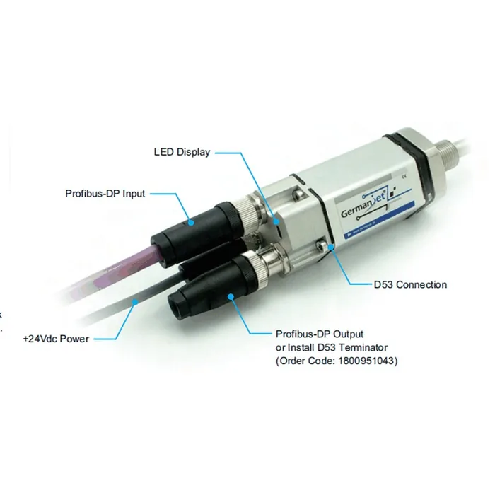
| Profibus DP | Yes | Built into the plug; ON at both ends, OFF in the middle | The device switched ON must remain powered |
| Modbus RTU (RS-485) | Yes | One 120 Ω at each end of the segment | Likewise linear topology; the same rule |
| EtherCAT | No | Point-to-point Ethernet links | Attend instead to IN/OUT daisy-chain order |
| PROFINET | No | Point-to-point Ethernet links + switching | Attend instead to single-segment cable length and topology configuration |
| SSI | Point-to-point link | Follow the host and sensor manuals | Do not reuse bus termination rules |
The core information of this table is: terminating resistors belong only to bus-type physical layers in which "several nodes share one differential pair". Ethernet-class protocols use point-to-point links; impedance matching is provided by the PHY transformers and the cable specification, and no external terminator is needed. Applying CAN experience to PROFINET, or conversely omitting termination on a CAN segment, are both common concept mix-ups. For the corresponding note on the PROFINET side see PROFINET Diagnostics and Topology: What's Really Going On.
The inverse relationship of bus length and baud rate
CAN and Profibus follow the same physical law: the higher the baud rate, the shorter the allowed segment. The reason is that the round-trip propagation time on the bus must fall within one bit time to complete arbitration or sampling; raising the rate shortens the bit time and the tolerable propagation delay shrinks with it. CANopen supports the baud-rate steps 10 / 20 / 50 / 125 / 250 / 500 / 800 / 1000 kbps precisely so that the engineer can choose a suitable rate for the actual cable length.
The correct engineering order is: measure the actual cable run first → back-calculate the highest usable rate for that length → then drop one step for margin. The usable length also depends on cable specification, node count and connector count, and should follow the master manual. For how to configure rate and address see CANopen Node Address and Baud Rate Configuration in Practice; for systematic troubleshooting of interference and earthing see Troubleshooting Fieldbus Interference: Grounding, Shielding, Topology. Related products: the 194 CANopen series and the 195 Profibus series.
Frequently Asked Questions
Q: Why must a bus terminating resistor be 120 Ω?
Because the shielded twisted-pair cable used on CAN, Profibus and RS-485 typically has a characteristic impedance of the order of 120 Ω. Only when the end load equals the cable characteristic impedance is the signal energy fully absorbed; a mismatch produces reflection, which superimposes on the following signal and causes waveform distortion and occasional bit errors.
Q: Why does it sometimes work without terminating resistors?
Over a short distance at low speed, the round-trip time of the signal is far shorter than one bit time, so the reflection has already decayed before the sample instant and the problem is masked. Raise the speed or extend the line and the reflection superposition lands on the sample point, producing the typical intermittent "it was always fine before" fault.
Q: What happens if three terminating resistors are fitted?
It over-matches: in parallel the total load impedance is too low, the driver's load capability is pulled down and signal amplitude is insufficient. This is more hidden than a missing terminator, because at low speed it often still works. About 40 Ω or lower with power off indicates too many have been fitted.
Q: How do I judge whether terminating resistors are in place as a pair?
Measure DC resistance between the differential pair with power off: about 60 Ω on the CAN side means both are in place; about 120 Ω means only one; hundreds of ohms and above means none at all; about 40 Ω or lower means over-matched. Measure with power off; if necessary unplug one end and measure the cable side alone.
Q: Do Ethernet-class fieldbuses also need terminating resistors?
No. EtherCAT and PROFINET use a point-to-point link structure; each cable segment connects only two ports, impedance matching is provided by the PHY transformers and the cable specification, and there is no bus-reflection problem. What they must attend to is single-segment cable length, cable category and topology configuration.
Related Products



Related Applications

Series 19D Split-Type Process Displacement Sensor Application Cases
View Details
Series 19F Flexible Process Displacement Sensor Application Cases
View Details
Series 19H Cylinder-Integrated Process Displacement Sensor Application Cases
View Details