
How to Connect Magnetostrictive Displacement Sensors to a Fieldbus: A Practical CANopen and EtherCAT Guide
After choosing analog or fieldbus for a magnetostrictive displacement sensor, the real trouble is "how to connect the bus". Many engineers on site get stuck on CANopen node addresses and PDO mapping, and on EtherCAT slave configuration. This article is not about product selection; it is about how to wire it, walking through both CANopen and EtherCAT and covering multi-magnet reading and a few pitfalls. For a selection comparison, go back to the Series 194 CANopen and Series 197 EtherCAT product pages.
First understand: what number the sensor puts on the bus
Inside a magnetostrictive displacement sensor, position is measured by a waveguide wire. The electronics head launches a current pulse; superimposed on the magnet's axial field, the waveguide "twists" at the overlap — that is the Wiedemann effect, and the torsional wave travels back along the wire to the electronics. Note that stretching of the material by a magnetic field is the magnetostrictive effect; torsion is the Wiedemann effect. They are different; do not mix them. The electronics records the time from pulse to echo and multiplies by the speed of sound to obtain magnet position. What the bus therefore emits is an absolute position value that is not lost on power-down, with no homing required — which is why it is less trouble than an incremental encoder.
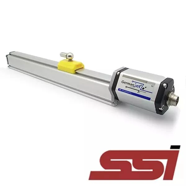
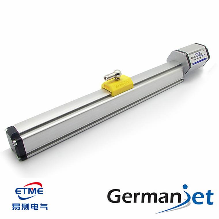 Figure 1: Germanjet Series 194 CANopen fieldbus magnetostrictive displacement sensor (slider magnet type)
CANopen: follow CiA DSP 406
Germanjet CANopen slaves follow the standard DSP 406 encoder/measuring-device profile; there is no proprietary protocol. On site, watch these points:
- Baud rate: 10 / 20 / 50 / 125 / 250 / 500 / 800 / 1000 kbps are all supported. On the shop floor I generally recommend 250k or 500k; 1M is too high and tends to drop frames on long cables and noisy cabinets.
- Node address: 1–127, set by DIP switch or software. Addresses on one bus must not clash; two same-address nodes flood error frames and drop out intermittently, so set and label every address before batch go-live.
- PDO and SDO roles: position values travel in TPDOs (sensor → master, process data, real time); parameters such as zero offset, measuring range and filtering travel in SDOs (configuration). Position rides a PDO cyclically or on event; polling position with SDO saturates the bus load — it is slow and wastes bandwidth.
- Position-value object: in the 0x6000 area, INT32; the unit depends on how you configure it — some are pulse counts, some are directly 0.01 mm. Confirm the range parameters before the host converts the number, or the value will be wrong.
- Update rate: set by transmission type + Event Timer. For cyclic synchronisation, set a synchronous mode; to transmit only when data change, set the event timer and save bus load.
Do not forget the two 120 Ω terminating resistors: one at each end of the bus; intermediate nodes do not add one. Forget them or put them in the wrong place and long-run communications will be intermittent.
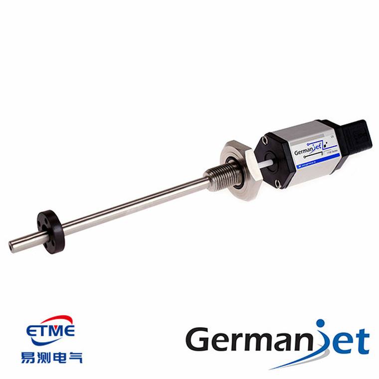 Figure 2: CANbus / CANopen profile magnetostrictive displacement sensor, with M12 bus-interface electronics head
EtherCAT: one cable carrying eight positions
I have Germanjet's EtherCAT slave description file (GJ EtherCAT 8ch V1.2) to hand, so the measured facts: Vendor ID is 0x000005FC, and the slave supports 8 channels. Position-value objects sit at 0x6030, with Position 1 to Position 8 underneath, all 32-bit DINT, mapped out in one go through PDO 0x1A01. In other words, one EtherCAT slave can pack the positions of up to 8 magnets into a single telegram; the master scans the cycle once and has them all, using distributed clocks (DC) for synchronisation, with jitter an order of magnitude smaller than CANopen.
Compared with CANopen, EtherCAT does not require you to worry about terminating resistors and node addresses; Wire slaves IN-to-Out, leave the last slave’s OUT open and fit no terminator; distributed clocks align the sampling instant across slaves, they do not cancel the sensor’s own delay. Cabling is a standard Ethernet daisy chain, which is simpler. The prerequisite is that your controller has an EtherCAT master — do not force it onto an old PLC that only has a CANopen port; if Series 194 is the right choice, choose 194.
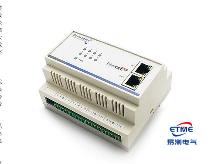 Figure 3: Germanjet 8-channel digital EtherCAT module, with multiple sensors on an EtherCAT network
How to read multiple magnets (multiple position magnets)
The Series 19 supports multiple magnets on one sensor, each measuring position independently — in the trade, asynchronous multi-magnet reading. The practical use is straightforward: clamp, injection and ejector positions on an injection molding machine would otherwise need three sensors; one multi-magnet unit now covers them. Combined with a Series 17 built into the cylinder, a machine's position feedback can save a good deal of cabling. In CANopen each magnet's position maps to a different sub-index; on EtherCAT they are Position 1–8 at 0x6030. Each magnet maps separately in the object dictionary and carries its own zero offset. The key is not to mount magnets too close: Series 19 analogue dual-magnet minimum spacing is 76 mm. At ≥76 mm the echoes are clearly separable in time; do not use the old 78 mm figure. Below the specified minimum the echoes overlap, causing position jumps or a "no position" report on that channel. Other series: confirm against that model’s catalogue.
The pitfalls most often met on site
- Wrong baud rate or node address — on power-up, first use a CAN analyser to look for a heartbeat; no heartbeat is usually one of these two.
- Terminating resistors forgotten or misplaced — intermittent long-run communications; first measure whether bus resistance is about 60 Ω (two terminators in parallel).
- One-size-fits-all screen earthing — bus cable and analog signal cable follow different rules: analog is single-end earthed (cabinet side) to avoid earth loops; CANopen / EtherCAT buses should have 360° bonding at both ends when the two ends are reliably at the same potential, so high-frequency interference can dissipate. Copying the analog method onto a bus makes immunity worse.
- Units not converted correctly — whether the position value is counts or mm was not confirmed, the host display is out by tens of times, and the closed loop flies off.
Practical tips for engineers
- The position magnet must not touch the measuring rod; the designed clearance between them must be maintained.
- Fix the magnet with screws, spacers and similar parts made of non-magnetic material, so that ferromagnetic parts do not disturb the measurement.
- An M6 hexagon-socket set screw is recommended for locking the magnet — this screw is not supplied with the sensor and must be provided by the user.
Frequently Asked Questions
Q: How do I set the CANopen node address and baud rate?
Node addresses run from 1 to 127 and are set by DIP switch or software. Addresses on one bus must not clash: two nodes sharing an address flood the bus with error frames and drop out intermittently, so set and label every address before batch go-live. Supported baud rates are 10 / 20 / 50 / 125 / 250 / 500 / 800 / 1000 kbps; on the shop floor 250k or 500k is generally recommended, since 1M tends to drop frames on long cables and in noisy cabinets. On power-up, first use a CAN analyser to look for a heartbeat — no heartbeat usually means one of these two settings is wrong.
Q: Why should position data not be polled with SDOs?
It is a division of labour: position values travel in PDOs, cyclically or on event, while SDOs are used only for configuration and maintenance. Polling position with SDOs saturates the bus load and is slow and wasteful. The position-value object sits in the 0x6000 area as INT32, and its unit depends on your configuration: pulse counts, or directly 0.01 mm. Confirm the range parameters before the host converts the value, or the display will be out by tens of times and the closed loop will fly off.
Q: Does EtherCAT need terminating resistors, and how many channels does one slave carry?
No terminating resistors are needed. EtherCAT wires slaves IN to OUT in a chain with the last slave's OUT left open, using a standard Ethernet daisy chain, and node addresses are not a concern either. One slave supports 8 channels: position-value objects sit at 0x6030 with Position 1 to Position 8 underneath, all 32-bit DINT, mapped out in one go through PDO 0x1A01, with distributed clocks providing synchronisation and jitter an order of magnitude smaller than CANopen. The prerequisite is a controller with an EtherCAT master.
Q: How many positions can one sensor measure, and how close can the magnets be?
Multiple magnets can be fitted to one sensor, each measuring position independently — asynchronous multi-magnet reading, supported by Series 19. In CANopen each magnet's position maps to a different sub-index; on EtherCAT they are Position 1 to 8 at 0x6030, each mapped separately in the object dictionary with its own zero offset. A typical use is covering clamp, injection and ejector positions on an injection molding machine with a single unit. The magnets must not be mounted too close, however: the Series 19 analogue dual-magnet minimum spacing is 76 mm. Below that the echoes overlap, causing position jumps or a no-position report on that channel.
Q: Should the bus screen be earthed at one end, the way analog cable is?
No. Bus cable and analog signal cable follow different rules: analog is single-end earthed at the cabinet side to avoid earth loops, while CANopen and EtherCAT buses should be bonded 360 degrees at both ends when the two ends are reliably at the same potential, so high-frequency interference has a path to dissipate. Copying the analog method onto a bus makes immunity worse. Also remember the two 120 ohm terminators, one at each end of the CAN bus with no resistor on intermediate nodes, and when in doubt measure whether bus resistance is about 60 ohm, the two terminators in parallel.
Related Products


Related Applications

Series 19D Split-Type Process Displacement Sensor Application Cases
View Details
Series 19F Flexible Process Displacement Sensor Application Cases
View Details
Series 19H Cylinder-Integrated Process Displacement Sensor Application Cases
View Details