
Self-Diagnostics of a Magnetostrictive Displacement Sensor: Four Levels of Saying Whether the Reading Is Trustworthy
A smart magnetostrictive displacement sensor answers not only "where" but "is this reading trustworthy". In displacement measurement, "smart sensor" has a fairly specific meaning: besides giving a position value, the sensor can report whether it can be trusted. A traditional analog sensor outputs only a current or voltage. When the reading is abnormal, there is no way to tell whether the measured mechanism truly moved or the sensor itself failed. A digital sensor with self-diagnostics can report magnet validity, over-range, signal quality, internal temperature and similar status together, turning "the reading is wrong" from a post-hoc inference into an advance warning. The trend is that this capability is moving from high-end models toward general-purpose ones as fieldbuses and IO-Link spread. Its value is not higher accuracy, but shorter fault-location time and support for predictive maintenance.
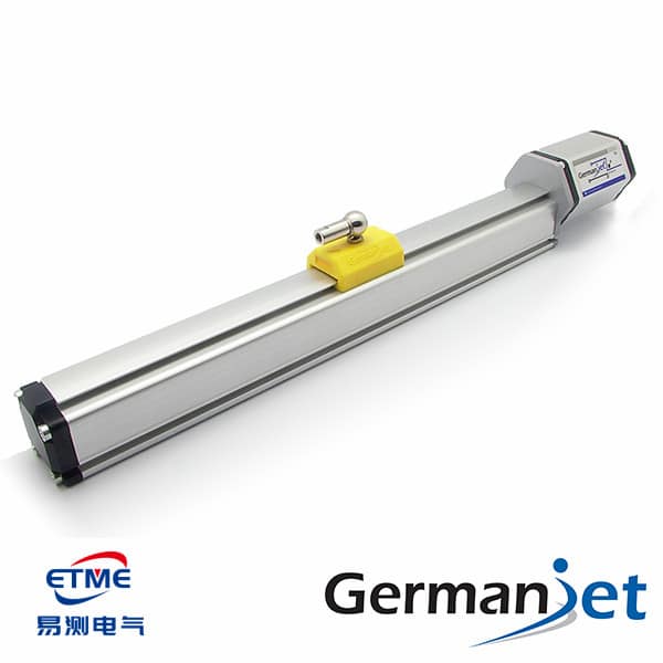
Four levels of self-diagnostic capability
| Level | Capability | Interface depended on | Meaning on site |
|---|---|---|---|
| L0 no diagnostics | Position value only | 4-20 mA / 0-10 V | Only coarse judgement via open-circuit or over-limit |
| L1 validity flag | Outputs magnet-loss, over-range and similar status bits | SSI / Modbus | Can distinguish "no signal" from "position is zero" |
| L2 events and alarms | Actively reports emergency telegrams / diagnostic events | CANopen / Profibus / PROFINET | Alarms can reach the HMI directly and locate the node |
| L3 parameterisation and self-description | Parameters can be read and written remotely; automatic write-back at replacement | IO-Link / fieldbus object dictionary | Fewer human set-up errors; shorter replacement time |
A higher level is not automatically more appropriate. A single-axis, low-cost, un-networked machine can reasonably stay at L0/L1; L2/L3 only produce a real return when the system can read and process diagnostic information. Interface capabilities are compared in how to network displacement sensors under Industry 4.0; the IO-Link parameter-storage mechanism is in IO-Link: the last hundred metres to the cloud. In short: magnet present, signal inside bounds, no over-range, case temperature in limit; one flag down points the fault to a part.
What a displacement sensor can diagnose about itself
- Magnet status: when the position magnet comes off, is offset or goes beyond the effective range, echo detection fails and an invalid flag can be given directly, rather than a seemingly plausible wrong position. Common installation-side problems are in five magnet installation pitfalls.
- Signal quality: a low echo amplitude usually foreshadows decaying magnet remanence, an excessive gap or an abnormality at the waveguide end — a typical early sign.
- Over-range and dead zones: unmeasurable regions exist at both ends of the rod. Entering that interval should raise a status, not extrapolate a value. The concept is in dead zones at both ends of the effective range.
- Internal temperature: temperature affects the speed of sound in the waveguide and zero drift. Reporting internal temperature helps judge whether reading drift is a thermal effect or a mechanical change. The basis is in self-heating, thermal equilibrium and the magnitude of temperature effects.
- Communications health: telegram error counts, loss of synchronisation and similar reflect the link rather than the sensor body. The troubleshooting idea is in troubleshooting fieldbus interference: grounding, shielding, topology.
Self-diagnostics change the order of troubleshooting
Traditional troubleshooting is "symptom-driven": the reading jumps → try items one by one. With diagnostic information it can become "status-driven": read the status word first, then decide which section to check. The effect on site labour is often more visible than an accuracy improvement. The complete troubleshooting flow should still follow common troubleshooting: inaccurate readings, jumps, no output, the signal-jump troubleshooting flow and FAQ round-up: 20 common questions — diagnostic information is a tool that shortens the flow, not a shortcut that replaces it.
The difference between diagnostic capability and a safety function
One boundary must be clarified: self-diagnostics are not functional safety. The purpose of diagnostics is to raise availability and maintainability. Functional safety requires that a defined safe state is entered when a fault occurs, involving system-level architecture, diagnostic coverage and a certification assessment. A single-channel sensor with diagnostics does not automatically meet a SIL rating because it can report status. Related concepts are in standards and certification: how to read functional safety SIL and redundant output and dual-channel safety design. When a safety rating is required, design it at system level; a redundant model such as the 16R redundant cylinder-integrated can be chosen.
Product and implementation suggestions
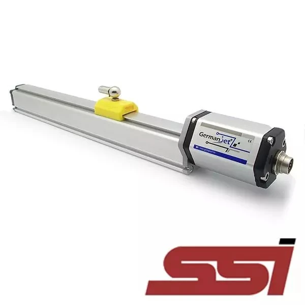
Fieldbus models with an object dictionary and diagnostic telegrams include the Series 194 CANopen (DSP406 profile, emergency telegrams supported), the Series 195 Profibus (DP diagnostics), the Series 197 EtherCAT and the 199PROFINET series (device-level diagnostics and topology information). For digital reading with a compact structure, the Series 192 SSI can be used. In analog applications that need to keep basic diagnostics, set open-circuit and over-limit criteria on the controller for the Series 191 analog. The architecture for collecting and analysing diagnostic data is in IIoT and edge computing: an architecture for getting position data to the cloud.
Practical tips for engineers
- The Series 19 analog programming tool can set the zero and end values anywhere within the nominal factory stroke range.
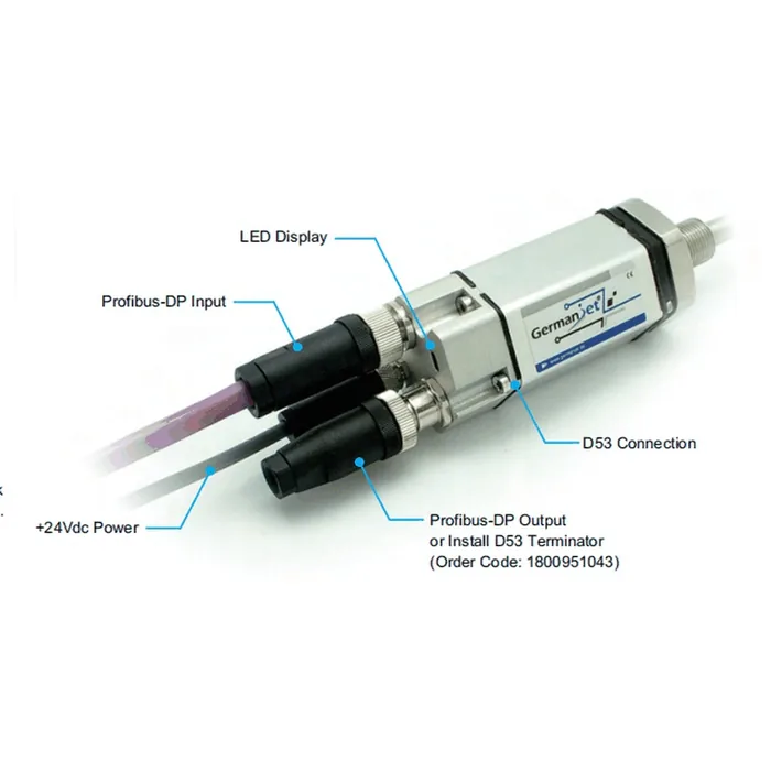
- The Series 19 Profibus simulator can check sensor functions, read magnet positions and diagnostic data, and change the slave address.
Frequently Asked Questions
Q: What can a displacement sensor's self-diagnostics diagnose?
Common items include magnet status (come-off, offset, beyond the effective range), echo signal quality, over-range and dead-zone indication, internal temperature, and communications health (telegram error count, loss of synchronisation). The first items reflect the sensor body; the last reflects the link rather than the sensor.
Q: Does a self-diagnostic function amount to meeting functional safety?
No. Self-diagnostics raise availability and fault visibility. Functional safety requires that a defined safe state is entered on a fault, involving system-level architecture, diagnostic coverage and a certification assessment. A single-channel sensor with diagnostics does not automatically meet a SIL rating because it can report status.
Q: Does an analog sensor have no diagnostic capability at all?
Only a coarse judgement is possible. 4-20 mA can use below 4 mA as open-circuit and above the upper limit as over-range, but cannot distinguish whether the measured mechanism truly moved or the sensor failed. Distinguishing those two needs a validity flag or a fieldbus diagnostic telegram.
Q: What should the controller do when an invalid-position flag is read?
Hold the last valid value or enter a controlled stop. Never treat 0 as a real position and continue the motion. This default behaviour must be designed explicitly in the PLC program, and the diagnostic field must be mapped to an HMI alarm screen; otherwise a telegram running on the bus that nobody reads is the same as none.
Related Products


Related Applications

Series 19D Split-Type Process Displacement Sensor Application Cases
View Details
Series 19F Flexible Process Displacement Sensor Application Cases
View Details
Series 19H Cylinder-Integrated Process Displacement Sensor Application Cases
View Details