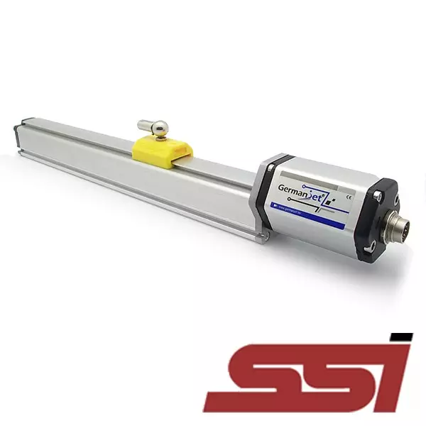
Series 19 SSI digital interface magnetostrictive displacement sensor
SSI synchronous serial output, D70 7-pin connector
The Series 19 SSI version (order code 192) uses an SSI synchronous serial interface to output absolute position, supporting binary / Gray code formats and 8-32 bit data lengths. Fitted with a 7-pin D70 male connector and a built-in LED diagnostic indicator, IP67 protection. High noise immunity, suitable for long-distance transmission and multi-axis synchronous applications.
Product Overview
The Series 19 SSI version (order code 192) uses an SSI synchronous serial interface that transmits the absolute position value at high speed over differential clock / data lines. Binary or Gray code data formats are supported, with a selectable data length of 8-32 bit and a selectable resolution of 1 / 2 / 5 / 10 / 20 / 50 / 100 µm.
The data rate adapts automatically to cable length: up to 1000 kBd at <3 m, 400 kBd at <50 m, 300 kBd at <100 m, 200 kBd at <200 m and 100 kBd at <400 m. Update frequency varies with stroke: up to 3.7 kHz for a 300 mm stroke and 0.5 kHz for a 5000 mm stroke.
Fitted with a 7-pin D70 male connector, IP67 protection (when the connector is properly mated). Red and green LED diagnostic indicators are built into the sensor head: green on / red off means normal operation, green on / red on means no magnet detected. The cable shield must be soldered to the connector shell and grounded at the controller side.
Operating Principle
Building on the standard magnetostrictive measurement principle, the Series 19 SSI version encodes position as SSI (Synchronous Serial Interface) synchronous serial data. The controller drives the sensor through the differential clock lines (yellow/green) of the D70 socket, and the sensor returns the absolute position value on the data lines (black/white) (Gray code or binary, MSB first, monostable trigger time minimum 48 µs). Absolute position is obtained without a reference homing run.
Typical Applications
Technical Specifications
| Ordering Code | 192 |
|---|---|
| Output | SSI synchronous serial output |
| Measured Data | Linear displacement |
| Data Format | Binary or Gray code |
| Data Length | 8 – 32 bit |
| Data Rate | Cable length <3 m: 1000 kBd / <50 m: 400 / <100 m: 300 / <200 m: 200 / <400 m: 100 kBd |
| Update Rate | Stroke 300 mm: 3.7 kHz / 750 mm: 3.0 / 1000 mm: 2.3 / 2000 mm: 1.2 / 5000 mm: 0.5 kHz |
| Resolution | 1 / 2 / 5 / 10 / 20 / 50 / 100 µm selectable |
| Repeatability | Full scale < ±0.001% (min. ±2.5 µm) |
| Non-Linearity | Full scale < ±0.01% (min. ±40 µm) |
| Update Time | 0.5ms(≤1200mm)/ 1.0ms(≤2400mm)/ 2.0ms(≤4800mm)/ 5.0ms(≤7600mm) |
| Power Supply | +24Vdc(20.4 – 28.8Vdc) |
| Input Protection | Polarity protection to -30 Vdc, overvoltage protection to 36 Vdc |
| Power Consumption | 100 mA (depending on measuring range) |
| Dielectric Strength | 500 Vdc (DC ground to machine ground) |
| Connector Options | 7-pin D70 male connector |
| Operating Temperature | -40 to +75 °C, 90% humidity, non-condensing |
| Protection Class | IP67 (when the connector is properly mated) |
| Vibration | 15 g / 10-2000 Hz / IEC standard 68-2-6 |
| Shock Resistance | 100 g (single shock) / IEC standard 68-2-27 (endurance) |
| EMC Compliance | Emission EN 61000-6-3, immunity EN61000-6-2, EN61000-4-2/3/4/6/8 |
Models and Output Signals
Dimensions and Wiring Diagrams
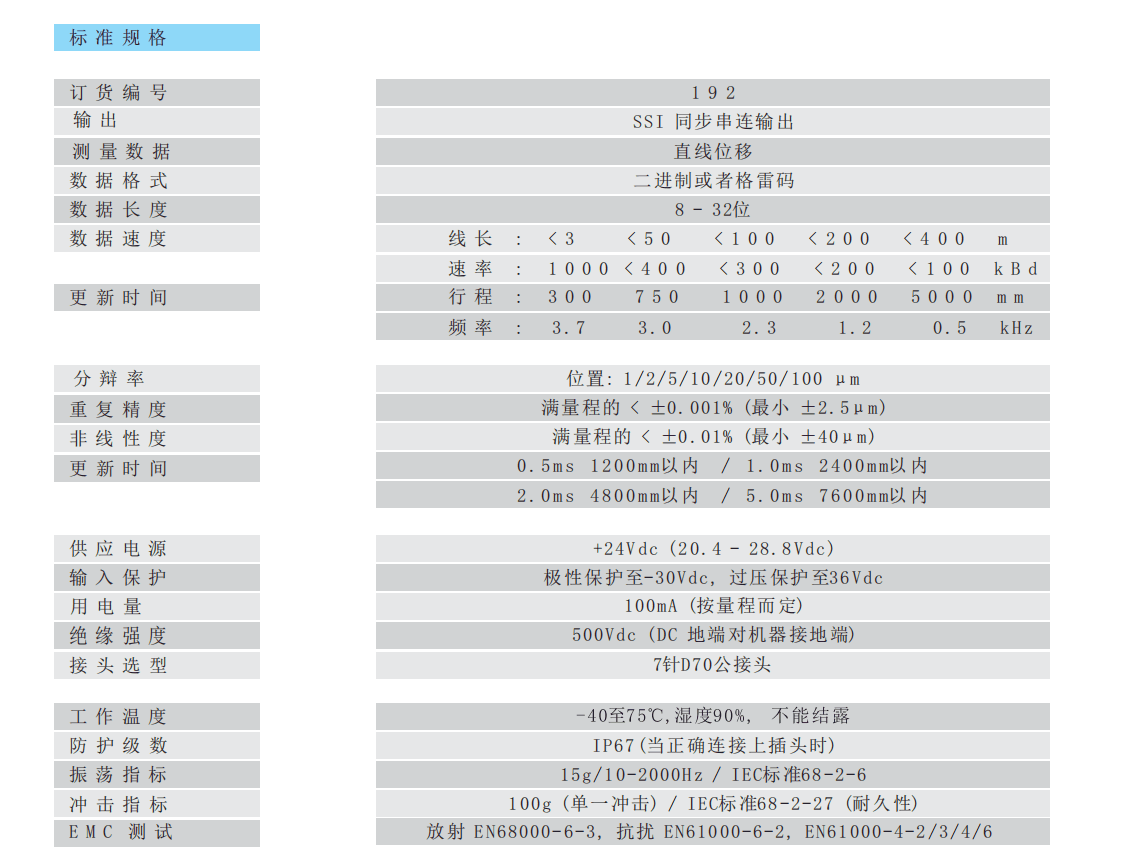
192 SSI standard specification table
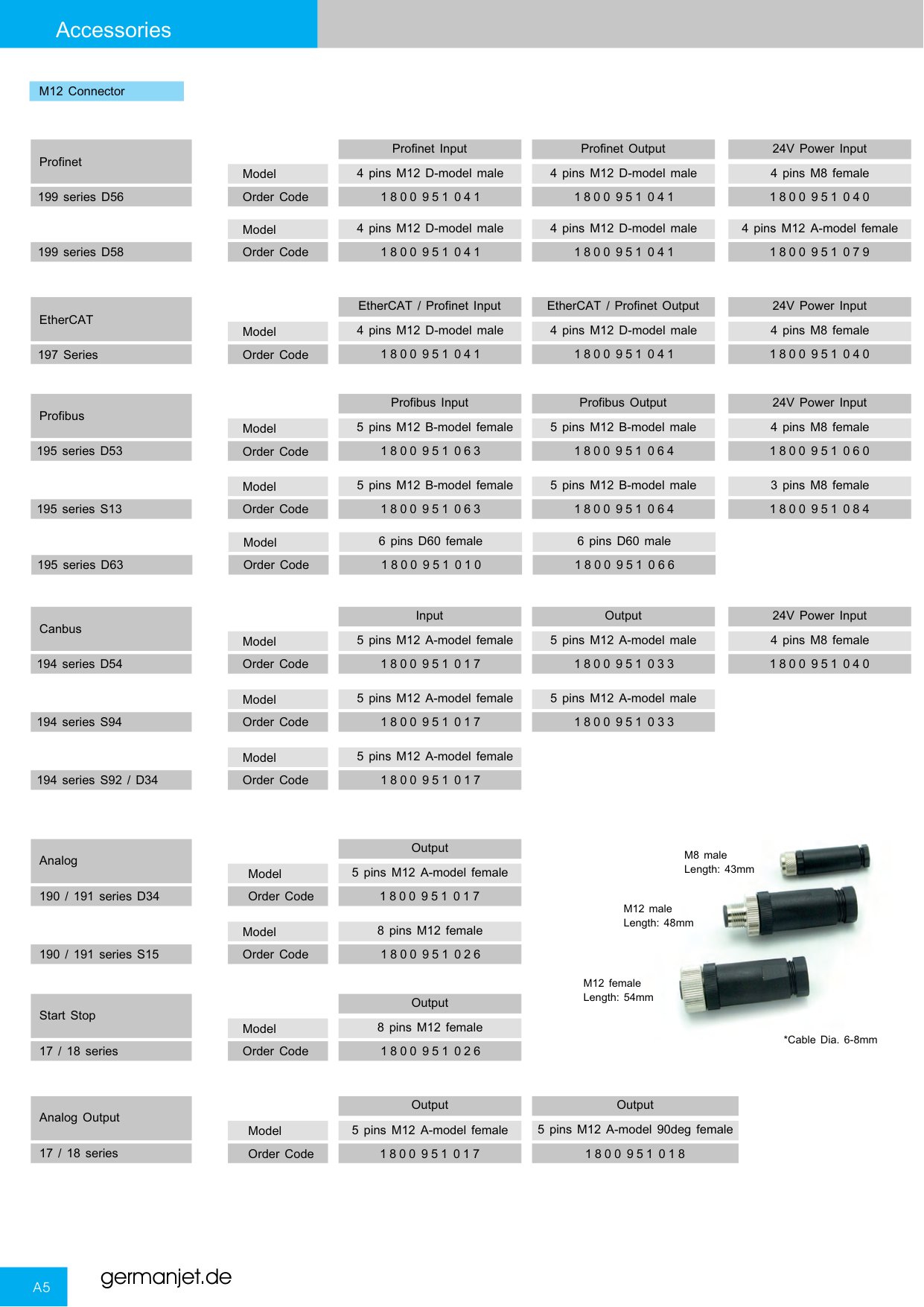
Series 19 connectors and socket types overview
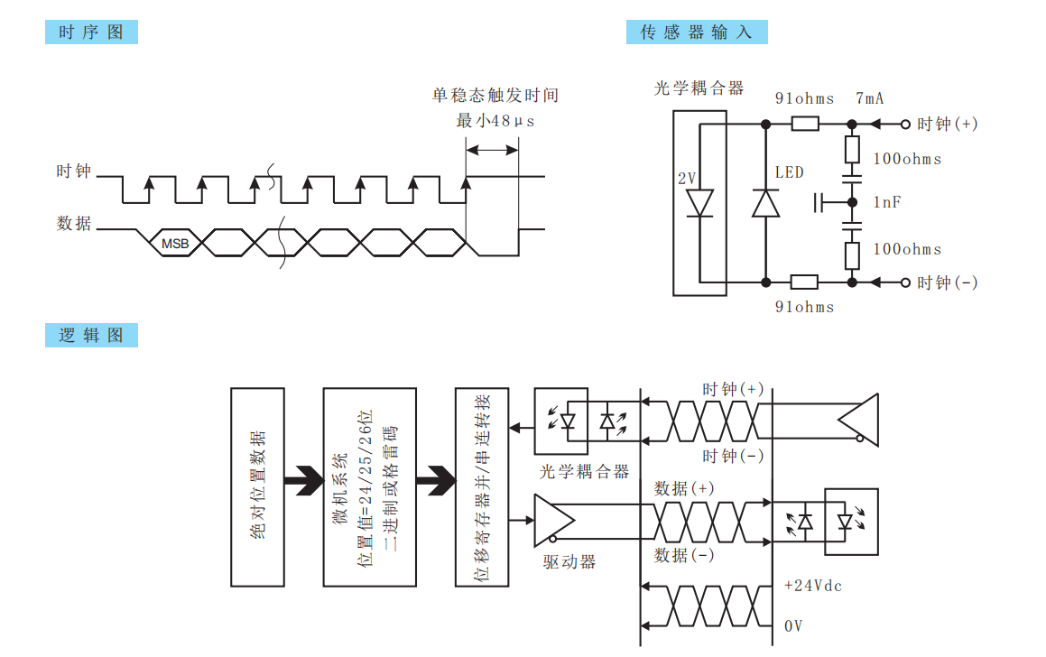
SSI timing diagram / sensor input circuit / logic block diagram
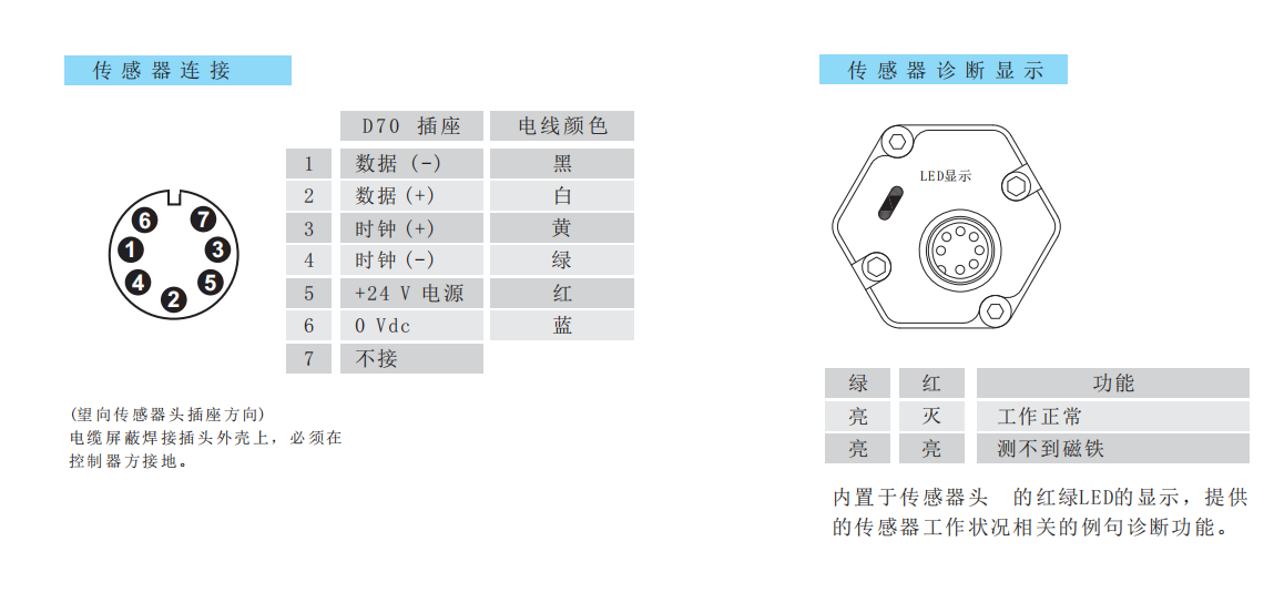
D70 socket pin assignment and LED diagnostic indication
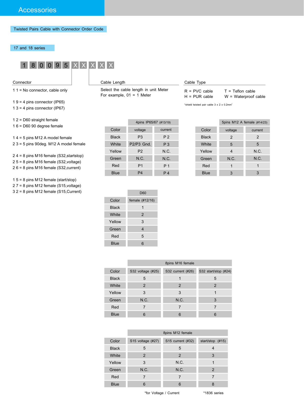
192 SSI digital interface wiring diagram
Installation Precautions
- SSI is an absolute position interface; position is restored without homing after a power loss.
- D70 socket pin assignment: 1 = data (−) black / 2 = data (+) white / 3 = clock (+) yellow / 4 = clock (−) green / 5 = +24 V supply red / 6 = 0 Vdc blue / 7 = not connected. The cable shield must be soldered to the connector shell and grounded at the controller side.
- Use shielded twisted pair with differential routing of clock and data lines, and avoid parallel runs with power cables.
- Make sure the data format (Gray code / binary) and resolution match the controller configuration. The minimum monostable trigger time is 48 µs.
- LED diagnostics on the sensor head: green on / red off = normal operation; green on / red on = no magnet detected (check the magnet ring position and distance).
- Regardless of the output interface, the physical installation of Series 19 must comply with the following: the ring magnet must not touch the rod; when built into a cylinder, piston-rod bore ≥12.7 mm (Ø10 rod); Series 19 in-cylinder is 300 bar working / 600 bar peak — never exceed that series peak; the rod must be protected against wear.
Pricing Notes
The price of the Series 19 SSI version depends on the data format, resolution, measuring range and mounting method. Please provide the controller model and interface requirements to obtain a quotation.



Technical Articles

How to Set the Injection to Packing Switchover: Time, Pressure or Position
Read More
Two Feedback Loops, Not One: Why Spool Position and Cylinder Position Are Measured Separately
Read More
SSI Displacement Sensor Wiring: Output Signals and How to Fix the Output at Selection
Read More
SSI Displacement Sensor Jumps After a Longer Cable: Drop the Clock to Match Length
Read More
Magnetostrictive output signals compared: eight interfaces and their trade-offs
Read More