SSI Displacement Sensor Wiring: Output Signals and How to Fix the Output at Selection
An SSI displacement sensor outputs a synchronous serial digital signal: one clock line plus one data line carrying Gray or binary position data. It has no power loop and it is not a fieldbus, so it cannot be freely converted to another signal the way a 4-20 mA loop can. The correct move is to fix the output at selection, not to convert it later. This article explains the SSI signal, why conversion is the wrong path, and the correct wiring and 4-20 mA practice.
What the SSI output actually is
The sensor returns a digital position frame bit by bit, synchronised to a clock supplied by the receiver — a PLC high-speed counting card or a dedicated SSI interface. The frame contains the position and status bits in Gray or binary. Because there is no power in the signal pair and the protocol is a pure data stream, the receiving device must have an SSI port; a normal analogue input card cannot read it.
Why SSI cannot simply be converted
- 4-20 mA is a powered loop with a standard load — it can be conditioned and isolated.
- SSI is clock + data: to "convert" it you would need a protocol translator module — non-standard, expensive, and one more failure point.
- What the site actually needs is usually "an input my system accepts", which is a selection decision, not a wiring fix.
The right move: fix the output at selection
| What the system needs | Choose this output |
|---|---|
| PLC analogue card | 4-20 mA / 0-10 V (four-wire) |
| High-speed counting / dedicated interface | SSI, start-stop |
| Fieldbus network | CANopen, Profibus-DP, EtherCAT, Profinet |
Confirm the controller side first, then pick the output — the same Germanjet sensor series is available with each of these outputs, so there is no need to convert anything.
If you already have SSI: how to connect it
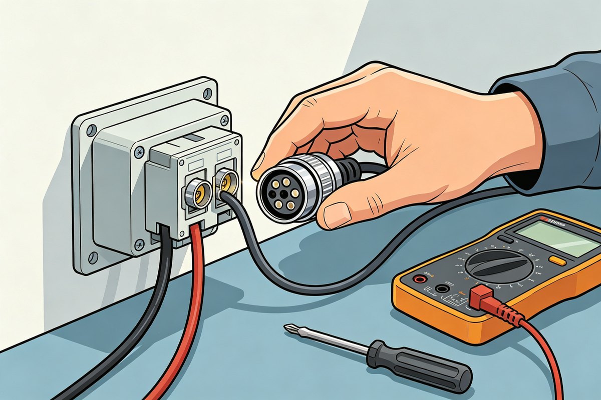
- Receiver must have an SSI interface — high-speed counter card or dedicated SSI module.
- Wire clock and data to the matching terminals; shield single-ended at the controller.
- Match clock frequency, bit length and Gray / binary to the sensor specification.
- Remember the sensor still needs its own 24 V supply.
4-20 mA correct practice (four points)
- Four-wire: supply pair and signal pair fully independent; never tie signal minus to 0 V.
- Load: connect to the analogue input within its load range.
- Shield: earth at the controller end only.
- Supply stable: a dipping 0 V shows up directly on the output.
One-line summary
SSI is a digital signal for dedicated SSI readers and cannot be freely converted; decide the output at selection. Choosing the output is step 3 of the five-step selection, and the wiring tables are in the complete wiring reference.
Frequently Asked Questions
Q: Can SSI be converted to 4-20 mA?
Not practically. SSI is clock plus data with no power loop; conversion needs a non-standard translator module. Fix the output at selection instead.
Q: What can read an SSI output?
A PLC high-speed counting card or a dedicated SSI interface. A normal analogue input card cannot read SSI.
Related Products
Related Applications
Series 16 Hydraulic Rod Magnetostrictive Displacement Sensor Application Cases
View Details
Series 19D Split-Type Process Displacement Sensor Application Cases
View Details
Series 19H Cylinder-Integrated Process Displacement Sensor Application Cases
View Details