
Magnetostrictive Displacement Sensor Series 192: SSI Timing, Gray Code and Data Bits
Series 16 SSI is 162, not 192. Electrics (D70, bit length, baud vs cable, 48 μs) match; mounting and pressure do not. See 162 SSI vs 192 SSI.
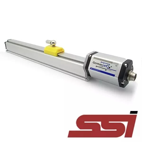
Series 192 is Germanjet’s SSI (Synchronous Serial Interface) output magnetostrictive displacement sensor. SSI is a point-to-point unidirectional digital interface: the master issues a clock pulse train and the sensor shifts position data out bit by bit on the clock edges. There is no bus arbitration, no device address and no protocol stack, so implementation is simple, latency is deterministic and immunity is better than analog, while still keeping the digital-transmission advantage of being unaffected by resistive voltage drop. For “one accurate position value, no fieldbus configuration wanted”, SSI is the least-fuss digital option.

Basic SSI timing
A complete SSI read can be split into four steps:
- Idle: the clock line stays high; the sensor continuously updates the position value internally;
- Latch: the master issues the first clock falling edge; the sensor latches the current position into the shift register and the position value is “frozen”;
- Shift out: the master continues to clock; the sensor shifts out one bit on each clock edge, usually MSB first;
- Monoflop timeout: after the data have been transferred the clock stops; after a monoflop time the interface resets and the next read can proceed.
Two constraints matter: clock frequency must match cable length (the longer the cable, the lower the allowed maximum clock frequency, because propagation delay and edge degradation destroy the sampling point); and enough monoflop time must be left between two reads — reading too fast causes data misalignment or residual bits from the previous frame. When a position value occasionally jumps to an abnormally large number in the field, check these two items first.
Cable length vs baud (same for 162 and 192)
| Cable length | Max data rate |
|---|---|
| < 3 m | 1000 kBd |
| < 50 m | 400 kBd |
| < 100 m | 300 kBd |
| < 200 m | 200 kBd |
| < 400 m | 100 kBd |
Minimum clock spacing 48 μs. 162 and 192 share this table; see 162 SSI vs 192 SSI. After a longer cable: SSI length versus rate.
Gray code versus binary
SSI position data have two encoding formats; choosing the wrong one reads a wrong value immediately.
| Item | Gray code | Binary |
|---|---|---|
| Change between adjacent values | Only 1 bit flips | Several bits may flip at once |
| Risk of a reading at the instant of a value change | Low; error of at most 1 least increment | High; an unrelated intermediate value may be read |
| Master processing | Gray-to-binary conversion required | Can be used directly |
| Typical use | High demand on sampling-instant reliability | When the master does not support Gray conversion |
The value of Gray code is to avoid transient misreads caused by several bits flipping at once. In binary, a change from 0111 to 1000 flips four bits at once; if sampling falls in the transition, 1111 or 0000 — values far from the truth — may be read. Gray code guarantees that two adjacent position values differ in only 1 bit, so even if the sampling instant is imperfect the error is limited to one least increment.
Engineering point: the sensor output encoding must match the master’s parse format. If the sensor is set to Gray and the master parses binary, readings show a “values jumping about but still patterned” oddity — the most typical SSI configuration error in the field. More on SSI timing and Gray conversion is in SSI synchronous serial interface: timing and Gray-code conversion.
Data bits versus resolution
The number of SSI data bits sets the representable position range. The bit count must cover the result of “measuring range ÷ resolution”: the finer the resolution and the longer the range, the more bits are needed. If the master is configured with fewer bits than the sensor actually outputs, the data read will be truncated; if more bits are configured, filler or status bits are read at the tail.
The first step of SSI commissioning is therefore always to check three things: data-bit count, encoding format and clock frequency. All three must be identical on master and sensor. The principle for choosing resolution steps (1 / 2 / 5 / 10 / 20 / 50 / 100 μm) is in The three accuracy figures — finer is not always better; too fine merely amplifies noise as well.
Where SSI sits against analog and fieldbus
| Comparison | SSI (192) | Analog (191) | Fieldbus (194/197 etc.) |
|---|---|---|---|
| Topology | Point-to-point, one pair per axis | Point-to-point, one pair per axis | Several nodes sharing a bus |
| Configuration effort | Low; three parameters suffice | Lowest; wiring is enough | High; GSD/XML/EDS configuration required |
| Immunity | Good (differential digital) | Fair; depends on shield earthing | Good |
| Long-cable transmission | Good, but clock frequency falls with length | 4-20 mA good, 0-10 V poor | Good, to the protocol specification |
| Diagnostic information | Limited (some status bits) | None | Rich |
| Multi-axis wiring | Independent wiring per axis | Independent wiring per axis | One bus in series |
| Read timing | Master-triggered, instant determined | Continuous output | Cyclic refresh or event-triggered |
The distinctive SSI advantage is that the read instant is decided by the master and is fully determined — whenever the master issues the clock, the position latched at that instant is what is read. That is useful for control logic that must align the sample tightly with other actions. The drawback is equally clear: each axis needs independent wiring; once the axis count rises, harness cost exceeds a fieldbus scheme.
Wiring and interference immunity
SSI uses differential signals (clock pair, data pair). Twisted-pair shielded cable must be used, with clock pair and data pair twisted independently; do not twist clock positive with data positive. Earth the shield at one end; the principle is in Shielded cable: single-end versus both-end earthing.
Differential transmission itself has strong common-mode immunity, but incorrect earthing can still take the receiver outside its common-mode input range. Where high-power inverters are present, keep signal cables in separate trunking from power cables; the mechanism is in EMC electromagnetic compatibility. The general troubleshooting order for common faults is in Fault finding.
Selection advice
Recommend the Series 192 SSI when: the controller (motion-control card, servo drive, dedicated controller) natively supports SSI encoder input; the axis count is small (typically single digits); digital accuracy is needed without introducing fieldbus configuration work; and the sample instant must be tightly aligned with the control cycle.
If the axis count is high and diagnostics and parameter read/write are needed, move to a fieldbus type: Series 194 CANopen, Series 197 EtherCAT or 199PROFINET. Horizontal comparison is in Comparing the whole fieldbus range. If the controller has only analog inputs, return to Series 191 analog. Interface comparison across the whole range is in Analog vs. digital across the whole range.
Practical tips for engineers
- The Series 19 analog programming tool can set the zero and end values anywhere within the nominal factory stroke range.
- The Series 19 Profibus simulator can check sensor functions, read magnet-ring positions and diagnostic data, and change the slave address.
Frequently Asked Questions
Q: Why is Gray code commonly used for SSI position data?
Gray code guarantees that two adjacent position values differ in only 1 bit, avoiding a severe misread when binary flips several bits at once and sampling falls in the transition. With Gray code, even if the sampling instant is imperfect, the error is limited to one least increment. The cost is that the master must convert Gray to binary.
Q: SSI readings jump but look patterned. What is wrong?
The most common cause is a mismatched encoding format — the sensor outputs Gray and the master parses binary, or the reverse. SSI commissioning should first check three items: data-bit count, encoding format and clock frequency. All three must be identical on master and sensor.
Q: SSI readings worsen after the cable is lengthened. What should be done?
First lower the clock frequency. The maximum allowed SSI clock frequency falls as cable length increases, because propagation delay and edge degradation destroy the sampling point. Enough monoflop time must also be left between two reads; reading too fast causes data misalignment.
Q: What are the advantages and disadvantages of SSI versus a fieldbus interface?
Advantages are very simple configuration (only data-bit count, encoding format and clock frequency), good immunity, and a fully determined read instant triggered by the master, which is convenient for aligning samples with other actions. Disadvantages are point-to-point topology, independent wiring per axis so harness cost exceeds fieldbus when the axis count is high, and limited diagnostic information.
Related Products



Related Applications

Series 19D Split-Type Process Displacement Sensor Application Cases
View Details
Series 19F Flexible Process Displacement Sensor Application Cases
View Details
Series 19H Cylinder-Integrated Process Displacement Sensor Application Cases
View Details