
How to Match a Magnetostrictive Displacement Sensor Output to Your Controller
The last step of choosing a hydraulic-cylinder magnetostrictive displacement sensor is the output interface; outputs fall into three classes: analog (4-20 mA / 0-10 V), point-to-point digital (SSI) and fieldbus (CANopen / Profibus / EtherCAT / PROFINET). The selection criterion is not “which is more advanced”, but three practical conditions: what input channels the controller has, how many axes the system has, and whether diagnostic information is needed. This article places Germanjet’s interface products in one matrix and gives a decision path that can be applied directly. Measuring performance is consistent across interface models — absolute position output, resolution steps 1 / 2 / 5 / 10 / 20 / 50 / 100 μm, repeatability of the order of ±0.002 mm, typical non-linearity <0.02% FS. The interface does not change measuring capability; it only changes how data are passed.
Product matrix overview
| Class | Product | Interface | Topology | Diagnostics | Typical fit |
|---|---|---|---|---|---|
| Analog | 191 | 4-20 mA / 0-10 V | Point-to-point | None (current loop can detect open circuit) | Single axis, existing plant, spare AI channels |
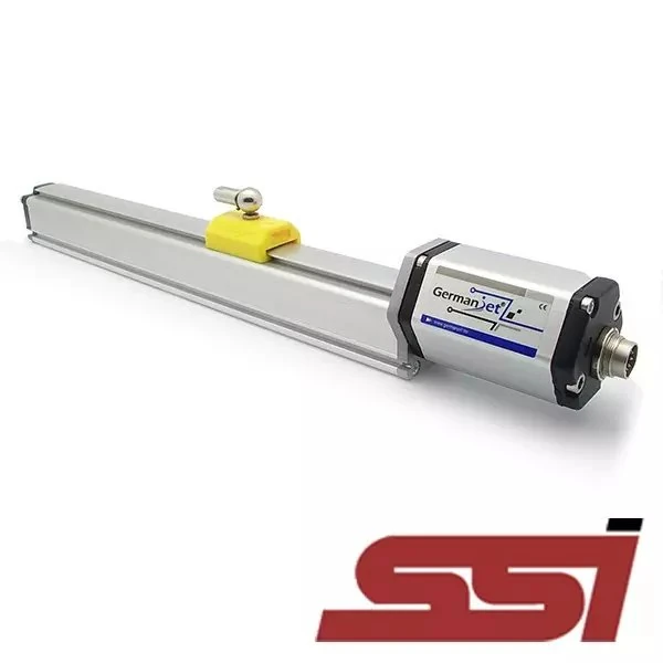
| Point-to-point digital | 192 | SSI displacement sensor | Point-to-point | Limited (status bits) | Motion-control card, Siemens PLC and other SSI masters, direct servo-drive connection |
| Fieldbus | 194 | CANopen (DSP406) | Linear shared bus | EMCY emergency message | Mobile machinery, multi-axis hydraulics |
| Fieldbus | 195 | Profibus DP (GSD) | Linear shared bus | Standard diagnostic telegram | Existing S7-300/400 lines |
| Fieldbus | 197 | EtherCAT (DC synchronisation) | Slaves in series | State machine + error counters | High-speed multi-axis synchronisation |
| Fieldbus | 198 | EtherCAT (single M12) | Slaves in series | As 197 | Tight space, dense nodes |
| Fieldbus | 199PROFINET | PROFINET (IRT) | Ethernet | Rich diagnostics, topology identification supported | New Siemens-system lines |
All these models share the same measuring performance; the magnetostrictive displacement sensor's accuracy does not change with the interface.
Detailed explanations of each model: Series 191 analog explained, Series 192 SSI explained, Series 194 CANopen explained, Series 195 Profibus explained, Series 197 EtherCAT explained, Series 198 single M12 explained, 199PROFINET explained.
The essential difference between analog and digital
| Comparison | Analog output | Digital output (SSI / fieldbus) |
|---|---|---|
| Information carrier | Continuous current or voltage value | Discrete digital encoding |
| Transmission degradation | Affected by resistive voltage drop and interference | Digital signal, unaffected by amplitude degradation |
| Chain accuracy ceiling | Limited by PLC analog input-card resolution | Set by sensor resolution |
| Diagnostic information | Essentially none | Yes; status and error codes can be read |
| Multi-position reading | One channel can output only one position | Several position values can be mapped |
| Integration effort | Lowest; wiring is enough | Configuration required (EDS/GSD/ESI/GSDML) |
| Multi-axis wiring | A pair of wires per axis | Fieldbus types can share a cable |
One point is easily missed: final accuracy of an analog chain is not set by the sensor, but by the weakest link in the whole chain. Sensor non-linearity is <0.02% FS; if the PLC AI card has only 12-bit resolution, whole-chain accuracy is limited by the AI card. A digital interface does not have this problem — whatever the sensor calculates is what the controller reads. How to read the accuracy figures is in The three accuracy figures; the division of output modules inside the electronics head is in What is inside the electronics head.
A three-step decision path
Step 1: look at what the controller has. This is the strongest constraint. Controller has only analog input cards → 191; has an SSI encoder interface → 192; has a CAN port → 194; is an S7-300/400 Profibus master → 195; is an S7-1200/1500 PROFINET → 199PROFINET; is an EtherCAT master → 197 or 198. Adding a gateway across systems is a last resort: a gateway means one more fault point, one more layer of delay, and one more set of configuration to maintain.
Step 2: count the axes. At 1–2 axes the harness cost of analog or SSI is acceptable; once the axis count reaches 4–6 and above, the fieldbus wiring advantage starts to show; above a dozen axes, analog AI modules and harness cost are usually no longer reasonable.
Step 3: confirm whether diagnostics and multi-position are needed. Need to read sensor status and error codes, or to read several magnet-ring positions on one waveguide wire (principle in Multi-magnet / multi-position measuring principle), must go digital; analog cannot do it.
The original framework of this decision path is in Selecting a magnetostrictive displacement sensor: 4-20 mA analog or CANopen fieldbus.
Common misjudgements and corrections
- “Fieldbus is more accurate than analog” — not accurate. The sensor’s measuring accuracy is independent of the interface. The fieldbus advantage is that it avoids extra degradation from the transmission chain and the AI card, not that it raises the sensor’s own capability.
- “Analog is outdated; new projects should all go fieldbus” — does not hold. On single-axis projects whose controller has only AI channels and whose commissioning window is tight, analog has the lowest integration cost and is still a reasonable choice.
- “Once EtherCAT is on, position refresh is faster” — a short bus cycle does not mean a high sensor update rate. Magnetostrictive update rate is constrained by measuring range, typically about 0.5 ms to 5 ms depending on range; a cycle set shorter than the update rate will only repeatedly read the same value. Matching methods are in Matching response time to the control cycle.
- “0-10 V and 4-20 mA are much the same” — the difference is large. The live zero of 4-20 mA can distinguish “position at zero” from “the cable is broken”; 0-10 V cannot. 4-20 mA falls below 4 mA on an open circuit so the controller flags a line fault; 0 V cannot be told from true zero. See Series 191 analog wiring in practice.
Interface and mounting form are two independent dimensions
Selection easily mixes “interface” with “mounting form”. In fact they are independent: mounting form decides where the sensor is fitted (cylinder-integrated, external, split, flexible); interface decides how data are passed. The same mounting form can take different interfaces, and the same interface can be used on different mounting forms.
Mounting-form selection is in two horizontal comparisons: in-cylinder options in Comparing the whole cylinder-integrated range: how to choose among 16/16R/17/17EX/19H; external options in Comparing the whole external range: how to choose among 13/18/19P/19F. The finer trade-off among fieldbus protocols is in Comparing the whole fieldbus range. Mapping interfaces onto the usual PLC Ethernet / serial / point-to-point classes, with pros and cons, is in output signals compared. General fieldbus wiring practice is in Fieldbus practical guide.
Practical tips for engineers
- Analog outputs are factory-calibrated slightly wider than the nominal stroke; after installation the machine must be recalibrated.
- Two-point method: Slope = actual displacement ÷ (end-of-stroke reading − zero reading); Datum = Slope × zero reading; machine position = (Slope × current reading) − Datum.
- Example: zero reading 0.2 V; after moving 98 mm the reading is 9.5 V → Slope = 98 ÷ (9.5 − 0.2) = 10.537, Datum = 10.537 × 0.2 = 2.106.
Frequently Asked Questions
Q: How should the interface of a magnetostrictive displacement sensor be chosen?
Judge in three steps. Step 1: look at what input channels the controller has — analog inputs only, choose 191; SSI interface, choose 192; CAN port, choose 194; Profibus master, choose 195; PROFINET, choose 199PROFINET; EtherCAT master, choose 197 or 198. Step 2: look at axis count; from four or five axes up the fieldbus advantage is clear. Step 3: look at whether diagnostic information or multi-magnet reading is needed; if so, a digital interface is required.
Q: Is fieldbus measuring accuracy higher than analog?
The sensor’s own measuring accuracy is independent of the interface. The fieldbus advantage is that it avoids extra error from transmission-chain degradation and PLC analog input-card resolution, not that it raises sensor capability. Final accuracy of an analog chain is set by the weakest link; however accurate the sensor, it will be held by the input card.
Q: Should new projects all go fieldbus?
No. On single-axis projects whose controller has only analog input channels and whose commissioning window is tight, analog has the lowest integration cost: once the wiring is live there is a reading, and it is still a reasonable choice. Adding a gateway across systems in order to use fieldbus instead adds a fault point, delay and maintenance load.
Q: Are interface and mounting form the same selection dimension?
No; they are independent. Mounting form decides where the sensor is fitted (cylinder-integrated, external, split, flexible); interface decides how data are passed. The same mounting form can take different interfaces, and the same interface can be used on different mounting forms. They should be judged separately at selection.
Related Products


Related Applications

Series 19F Flexible Process Displacement Sensor Application Cases
View Details
Series 19P External Rod Process Displacement Sensor Application Cases
View Details
Series 16 Hydraulic Rod Magnetostrictive Displacement Sensor Application Cases
View Details