Series 19 Profibus bus magnetostrictive displacement sensor
Profibus-DP (EN 50 170), D53, up to 12 Mbit/s
The Series 19 Profibus version supports the Profibus-DP (EN 50 170) fieldbus protocol based on the RS-485 physical layer, with a maximum transmission rate of 12 Mbit/s. It has a D53 standard connector and provides a GSD device description file and LED diagnostics. An RS-485 four-wire network can establish up to 32 segment stations without a repeater. IP67 protection.
Product Overview
The Series 19 Profibus version is based on the Profibus-DP (EN 50 170) protocol and the ISO 74498 system standard, using the RS-485 physical layer for error-free data exchange at up to 12 Mbit/s.
The sensor is fitted with a standard D53 connector and is supplied with a GSD device description file and LED diagnostics. Using a 4-wire RS-485 network, up to 32 segment stations can be set up without installing any repeater.
Network connection is via the D61 daisy-chain connector, D62 bus connector and D60 terminating connector, making installation quick and convenient. IP67 protection for harsh industrial environments.
Operating Principle
Building on the standard magnetostrictive measurement principle, the Series 19 Profibus version implements the Profibus-DP (EN 50 170) protocol stack (ISO 74498 system). Position data is exchanged over the RS-485 physical layer using error-free transmission technology at up to 12 Mbit/s. The sensor has a D53 standard connector and LED diagnostics, and an RS-485 four-wire network can establish up to 32 segment stations without a repeater.
Typical Applications
Technical Specifications
| Ordering Code | 195 |
|---|---|
| Output | Profibus-DP digital output |
| Measured Data | Linear displacement |
| Data Format | Profibus-DP(EN-50 170) |
| Interface | Profibus-DP system: ISO 74498 |
| Transmission Speed | Up to 12 Mbit/s |
| Resolution | Position: 5 µm / can be freely changed by the user via the GSD file |
| Repeatability | < ±0.001% of full scale (min. ±2.5 µm) |
| Non-Linearity | < ±0.01% of full scale (min. ±50 µm) |
| Update Time | 0.5ms(≤500mm) / 1.0ms(≤2000mm) / 2.0ms(≤4500mm) / 3.1ms(≤7600mm) |
| Power Supply | +24Vdc(20.4 – 28.8Vdc) |
| Input Protection | Polarity protection to -30 Vdc, overvoltage protection to 36 Vdc |
| Power Consumption | 100 mA (depending on measuring range) |
| Dielectric Strength | 500 Vdc (DC ground to machine ground) |
| Connector Options | D53 connector |
| Operating Temperature | -40 to +75 °C, 90% humidity, non-condensing |
| Protection Class | IP67 (when the connector is properly mated) |
| Vibration | 15 g / 10-2000 Hz / IEC standard 68-2-6 |
| Shock Resistance | 100 g (single shock) / IEC standard 68-2-27 (endurance) |
| EMC Compliance | Emission EN61000-6-3, immunity EN61000-6-2, EN 61000-4-2/3/4/6/8 |
Models and Output Signals
Dimensions and Wiring Diagrams
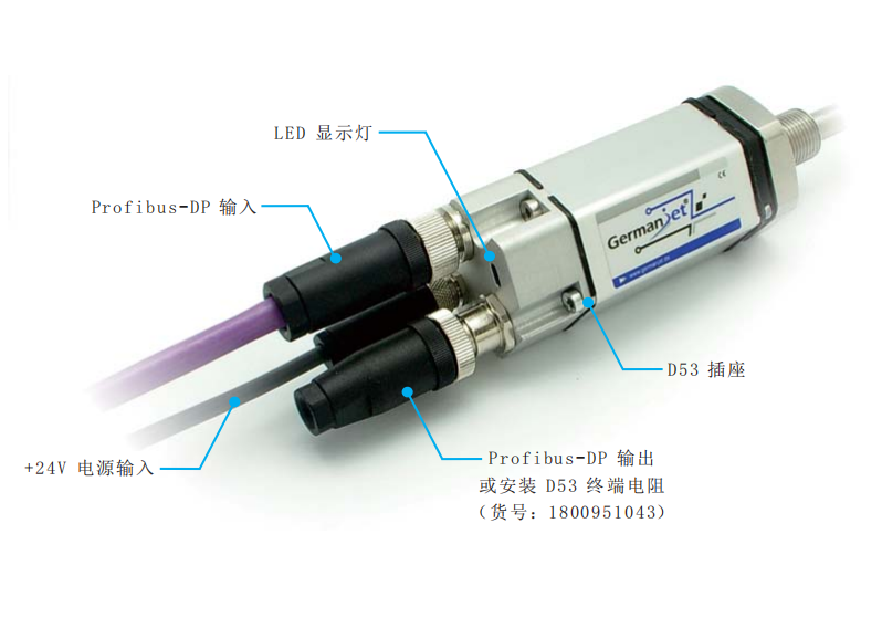
195 Profibus magnetostrictive displacement sensor photo
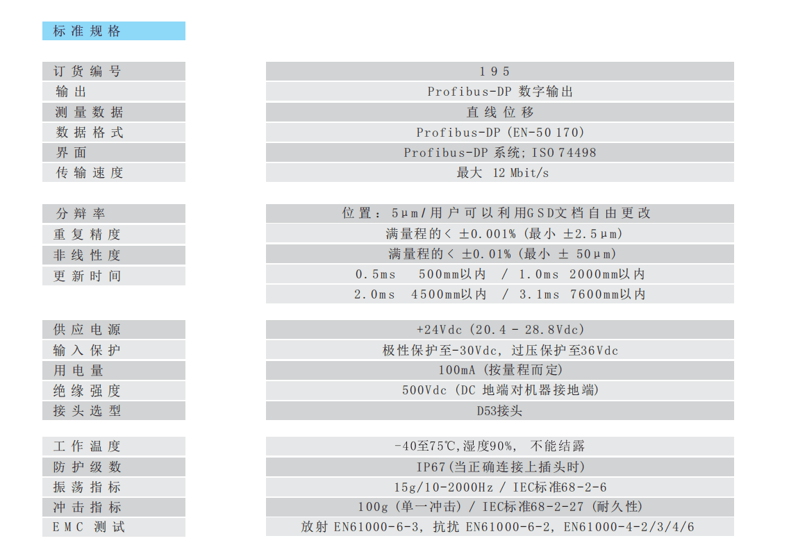
195 Profibus standard specification table
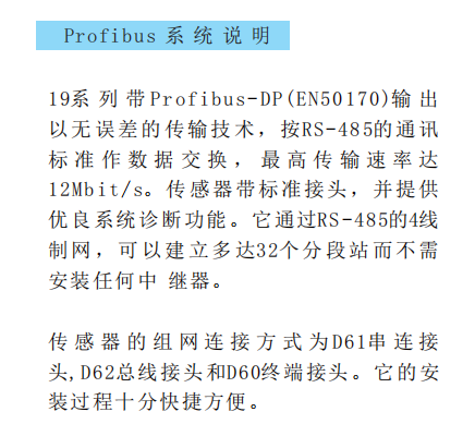
Profibus system description (RS-485 / 12 Mbit/s / 32 segments)
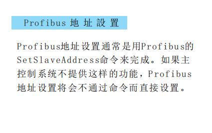
Profibus address setting (SetSlaveAddress)
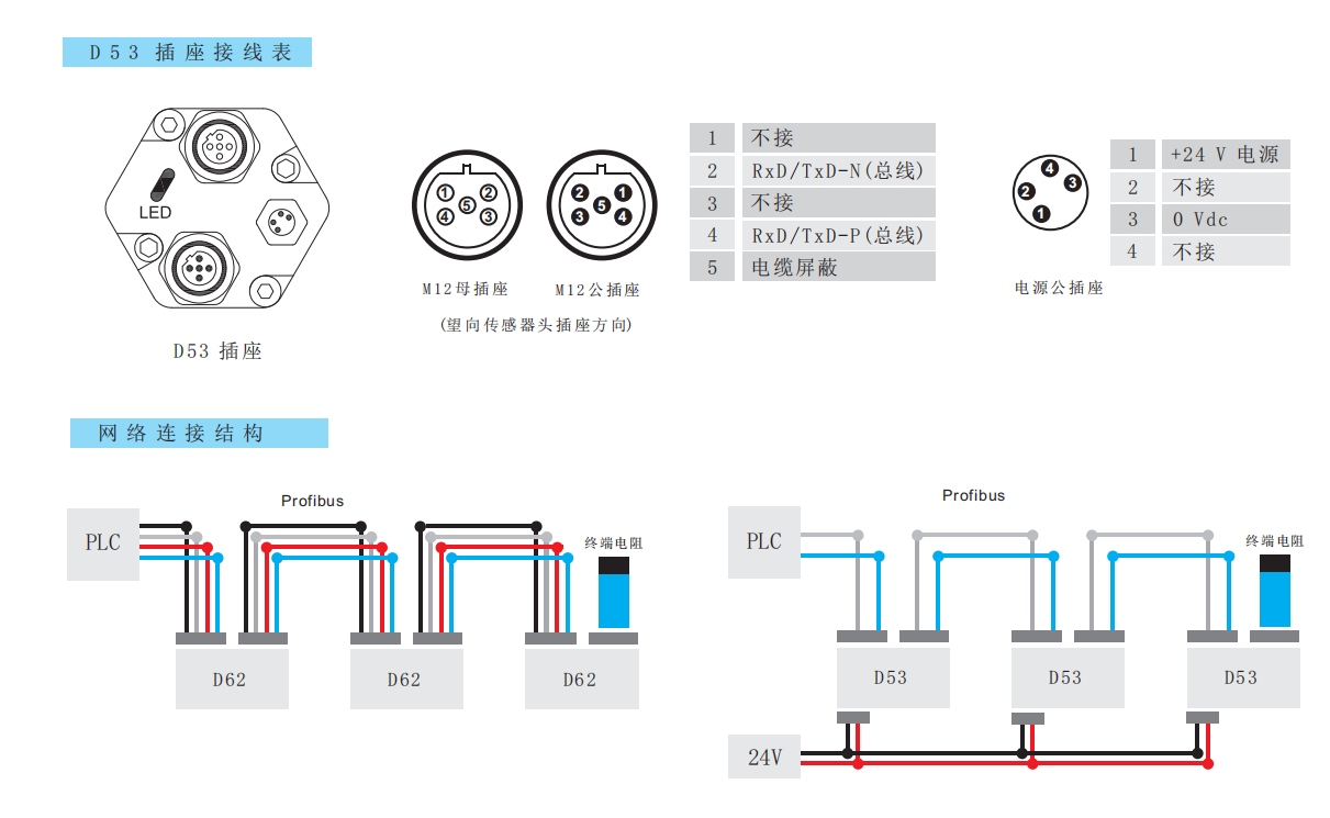
D53 socket wiring table and network connection structure
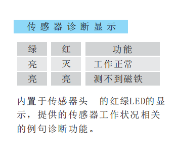
Sensor diagnostic LED indication
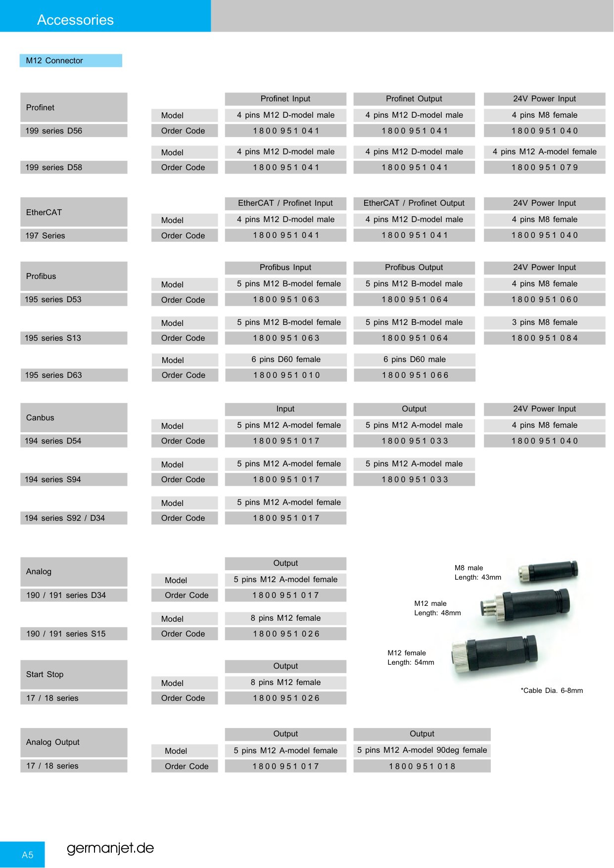
Series 19 connectors and socket types overview
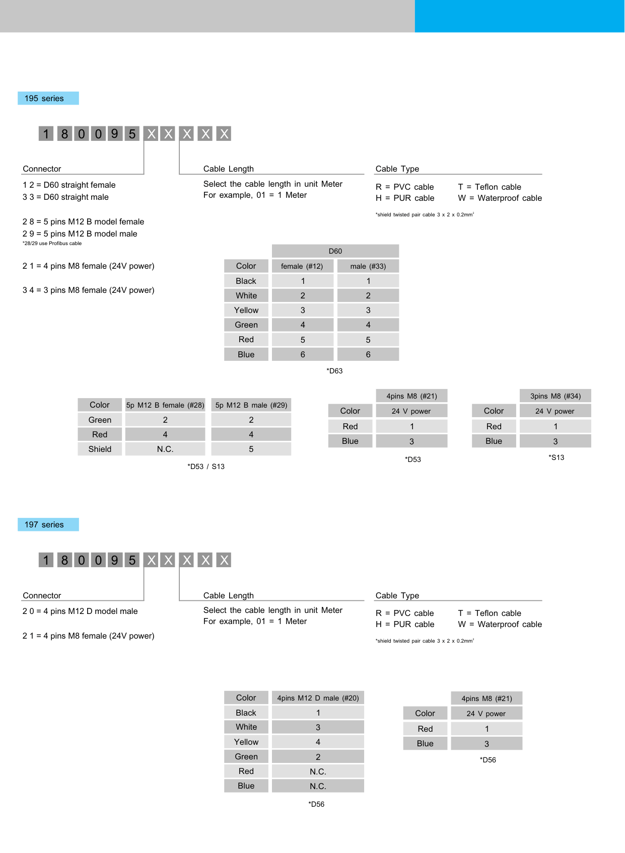
195 Profibus bus wiring diagram
Installation Precautions
- On a Profibus DP network the station address and baud rate must be set correctly. The address is normally set using the Profibus SetSlaveAddress command; if the master system does not provide this function, the address can also be set directly by command.
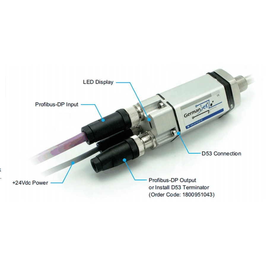
- D53 socket pin assignment (looking at the sensor head socket): data side M12 socket - 1 = not connected / 2 = RxD/TxD-N (bus) / 3 = not connected / 4 = RxD/TxD-P (bus) / 5 = cable shield; power side socket - 1 = +24 V supply / 2 = not connected / 3 = 0 Vdc / 4 = not connected.
- Network connection options: D61 daisy-chain connector, D62 bus connector, D60 terminating connector. D53 terminating resistor order number **1800 951 043**.
- The sensor head has built-in red/green LED diagnostics: green on / red off = normal operation; green on / red on = no magnet detected. Diagnostic functions are provided for fast on-site troubleshooting.
- Use dedicated Profibus shielded twisted pair cable (A/B lines) and avoid parallel runs with high-power lines. Import the GSD file into the master and verify the slave parameters and diagnostics.
- Regardless of the output interface, the physical installation of Series 19 must comply with the following: the ring magnet must not touch the rod; when built into a cylinder, piston-rod bore ≥12.7 mm (Ø10 rod); Series 19 in-cylinder is 300 bar working / 600 bar peak — never exceed that series peak; the rod must be protected against wear.
- Accessory connectors: 1800 951 017 / 033 / 040 (M12 / M8 classes), D53 terminator 1800 951 043, D62 1800 951 028. Profibus programmer 1700 951 032.
Pricing Notes
The price of the Series 19 Profibus bus version depends on the communication protocol, measuring range and mounting method. Please provide the master brand and bus requirements to obtain a quotation.



Technical Articles
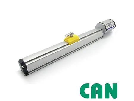
Magnetostrictive Displacement Sensor Fieldbuses: CANopen vs Profibus for Position Feedback
Read More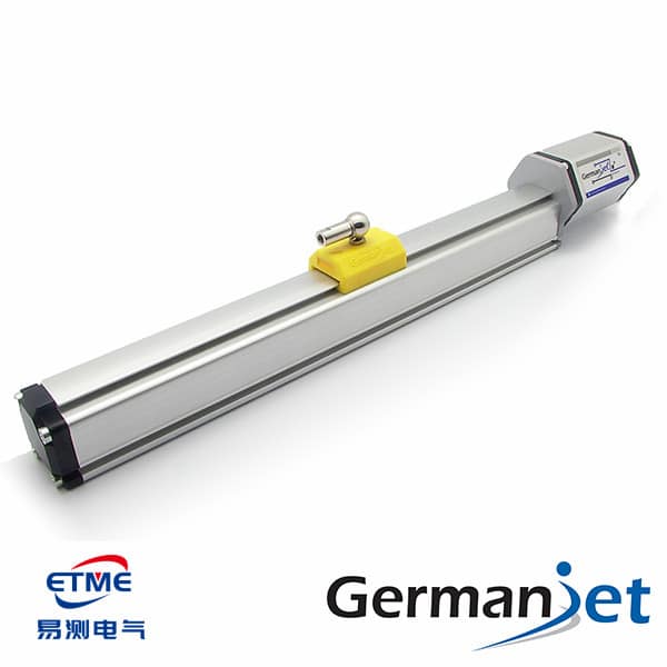
Self-Diagnostics of a Magnetostrictive Displacement Sensor: Four Levels of Saying Whether the Reading Is Trustworthy
Read More
How to Network Displacement Sensors Under Industry 4.0
Read More
Displacement Sensor Bus Interference: Reflection, Earthing, Routing in Order
Read More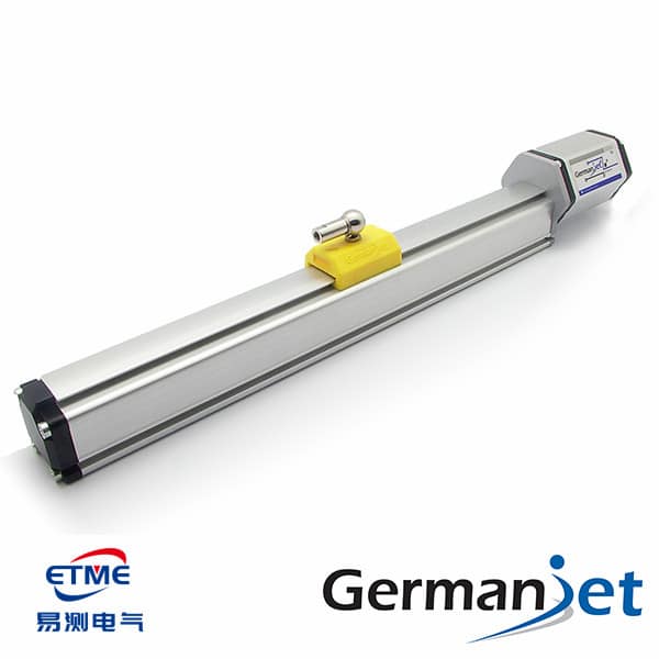
Choosing a Displacement Sensor Fieldbus: Which Bus My PLC Supports
Read More