
How to Network Displacement Sensors Under Industry 4.0
Networking a magnetostrictive displacement sensor is about making its parameters readable, not only moving one position value onto the bus. In an Industry 4.0 context, "networking the sensor" is not about adding an Ethernet port. It is about turning the position quantity from a one-channel analog signal that carries only a number into a device object with an address, parameters and diagnostics. The trend is reasonably clear at field level: analog (4-20 mA / 0-10 V) handles the most basic closed-loop feedback; digital fieldbuses (CANopen / Profibus / EtherCAT / PROFINET) take on multi-axis and real-time control; IO-Link fills in parameterisation and status reporting over the "last hundred metres". Because these sensors already output absolute position and need no homing, the migration cost along this path is relatively low — the control logic does not have to rebuild the position reference because of a networking retrofit.
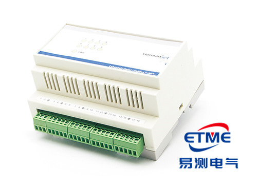
Three layers of meaning in networking: value, parameters, status
Unpacked, "networking" contains at least three independent things:
- Value transmission: the position reading is delivered to the controller. Analog already solved this.
- Parameterisation: range, zero offset, resolution step and filter settings can be read and written remotely, so a replacement does not need dismantling and re-adjustment.
- Status and diagnostics: magnet loss, weak signal, over-range, internal temperature and similar status can be read by the higher-level system, rather than being inferred only from "the reading is wrong".
An analog interface can only do the first; unidirectional digital interfaces such as SSI do the first and improve noise immunity; what truly completes the latter two is a fieldbus or IO-Link with an object dictionary or a parameter channel. That is why many retrofit projects "go on the network" without the expected return — they only digitised the value, while parameters and status remain a manual step. For the basic output-choice, see analog vs. fieldbus selection.
Comparing field-level access methods
| Access method | Value transmission | Remote parameterisation | Status / diagnostics | Typical role |
|---|---|---|---|---|
| 4-20 mA / 0-10 V | Supported (continuous) | Not supported | Coarse judgement via open-circuit / over-limit | Single-axis closed loop, legacy-machine retrofit |
| SSI | Supported (synchronous read) | Limited | Limited | Point-to-point high-refresh digital reading |
| Modbus RTU/TCP | Supported (registers) | Supported | Depends on the register map | Quick connection to an existing PLC/SCADA |
| CANopen (DSP406) | Supported (PDO) | Supported (object dictionary / SDO) | Supported (emergency telegram) | Multi-axis, cost-sensitive mobile equipment |
| Profibus DP (GSD) | Supported | Supported (configuration parameters) | Supported (DP diagnostics) | Existing automated lines |
| EtherCAT (DC) | Supported (high refresh) | Supported (CoE) | Supported | High real-time multi-axis synchronisation |
| PROFINET (IRT) | Supported (isochronous) | Supported | Supported (topology / device diagnostics) | Whole lines fused with the IT network |
| IO-Link | Supported (process data) | Supported (parameter storage / automatic write-back) | Supported (events) | The access point for taking the sensor layer to the cloud |
Implementation details of each protocol are covered in CANopen basics: the object dictionary and PDO/SDO, PROFINET basics: IRT and device-name assignment and Modbus RTU/TCP: how a PLC reads the position value.
Why IO-Link is called the "last hundred metres"
The Industry 4.0 data path is already mature on the MES/cloud side. The bottleneck has long sat at the bottom: sensors and actuators are often still dumb devices. The value of IO-Link is that a standard three-wire connection brings point-to-point sensors into a unified parameter and event system, which a master then aggregates onto the Ethernet backbone. For displacement measurement this means that resolution step, zero and alarm thresholds can be issued with a recipe, and parameters write back automatically at replacement, reducing human set-up error. The mechanism is in IO-Link: the last hundred metres to the cloud; for data layering and edge processing further up, see IIoT and edge computing: an architecture for getting position data to the cloud.
New data that becomes available after networking
Once a position sensor is networked, the incremental value is usually not the position value itself (analog already had that), but the accompanying information:
- Position curves: no longer only an instantaneous value, but an archivable full-stroke trajectory for process-consistency comparison;
- Device status word: signal strength, magnet validity, over-range flags and similar, which can trigger a warning directly rather than waiting for a stop;
- Communications quality: telegram loss rate, synchronisation jitter and similar, which reflect on-site routing and earthing quality and are objective evidence when troubleshooting interference; see troubleshooting fieldbus interference: grounding, shielding, topology.
The specific method for judging degradation from a position curve is in predictive maintenance: spotting equipment degradation in position data.
An evolution path for existing equipment
| Stage | Typical practice | Capability gained | Retrofit cost |
|---|---|---|---|
| Stage 1: digitise the value | Change analog to SSI / Modbus; leave the controller unchanged | Better noise immunity; readings can be archived | Low — mostly wiring and program changes |
| Stage 2: treat the device as an object | Change to a fieldbus type (CANopen / EtherCAT / PROFINET) | Remote parameterisation, diagnostic reporting, multi-axis synchronisation | Medium — needs configuration and master support |
| Stage 3: layer the data | Add an edge gateway; filter locally then send to the cloud | Trend analysis, cross-machine comparison | Medium — mainly software and network |
| Stage 4: close the loop back | Write analysis results back into process parameters and the maintenance plan | Predictive maintenance, process self-optimisation | High — involves management process |
A reminder: jumping stages is common but returns diminish. If site earthing and shielding have not been remediated, going straight to stage 3 leaves data quality too poor to support any analytical conclusion. For a transition scheme with several protocols coexisting, see multi-protocol gateways: one sensor family for several fieldbuses.
Networking-related confirmation items at selection
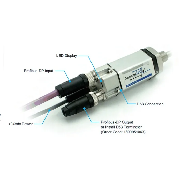
The selection judgement for a networking retrofit often sits on "what the master supports" rather than "what the sensor can do". Read the master’s available port first — SSI, CANopen, PROFINET or EtherCAT — because the sensor’s parameter set follows the protocol, not the housing. Selection guide: which fieldbus does my PLC support? gives a self-check order. On the product side, the Germanjet range covers the mainstream field-level interfaces: Series 194 CANopen (DSP406 profile), Series 197 EtherCAT (distributed clocks supported), 199PROFINET series (IRT isochronous), Series 195 Profibus (GSD configuration). Existing analog applications can transition with the Series 191 analog. Technical selection and configuration support in China is provided by Shenzhen Yice Electric Co., Ltd. (authorised distributor).
Frequently Asked Questions
Q: Is networking a displacement sensor just adding an Ethernet port?
No. Networking comprises three things: value transmission, remote parameterisation, and status and diagnostic reporting. Analog can only transmit the value; SSI improves noise immunity; what truly completes parameterisation and diagnostics is a fieldbus with an object dictionary, or IO-Link. Many retrofits only digitise the value, which is why the return is not felt.
Q: How do IO-Link and fieldbus relate?
IO-Link addresses the last hundred metres at sensor level. A standard three-wire connection brings point-to-point sensors into a unified parameter and event system, which a master then aggregates onto the Ethernet backbone. Fieldbuses (CANopen / EtherCAT / PROFINET and others) take on multi-axis real-time control. The two usually complement each other rather than replace each other.
Q: When converting a legacy machine to fieldbus, does the control logic have to be rewritten?
Magnetostrictive output is absolute position and the zero is not lost on power-down, so the position-reference logic does not need to be rebuilt at migration. The changes are mainly in communications configuration and data mapping. First confirm which fieldbus the PLC master supports; the master scan cycle also determines how fresh the data actually is.
Q: What use is the extra data after networking?
Mainly three kinds of accompanying information: an archivable full position curve (for process-consistency comparison); a device status word (magnet validity, over-range and similar, for earlier warning); and communications-quality figures (packet loss and synchronisation jitter, which can reflect earthing and shielding quality).
Related Products



Related Applications

Series 19D Split-Type Process Displacement Sensor Application Cases
View Details
Series 19F Flexible Process Displacement Sensor Application Cases
View Details
Series 19H Cylinder-Integrated Process Displacement Sensor Application Cases
View Details