
Displacement Sensor Gateways: Connect Direct Before Adding a Gateway
Pick a displacement sensor with the matching bus and connect direct; add a gateway only when no compatible port exists. On multi-protocol gateways, the conclusion first: if a sensor of the matching protocol can be chosen directly, do not add a gateway. A gateway essentially maps and moves data between the two protocols; it does not magically raise performance, and it necessarily brings three things: extra delay, an extra fault point, and a break in diagnostic information. Only in a few cases where a direct connection truly cannot be made is a gateway a reasonable choice. This article sets out the cost of a gateway, the application bounds and the configuration essentials; for the correspondence of protocols to products see Comparing the Whole Fieldbus Range.
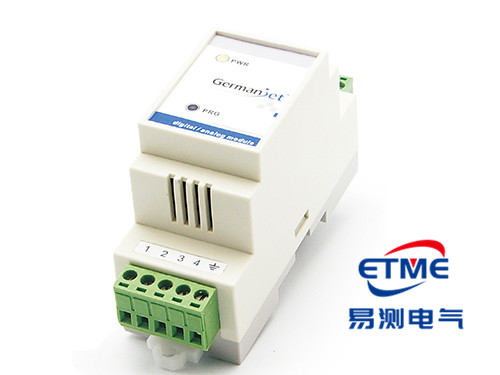
What a gateway does, and what it costs
Inside a gateway there are usually two independent protocol stacks plus a shared data area: one side acts as a slave, receives sensor data and writes it into the map area; the other side acts as a slave/master and hands the mapped data to the upper master. That structure determines three inherent costs:
- Delay is stacked and non-deterministic. Data passes through three stages: "sensor-side cycle → internal gateway move → master-side cycle". The three cycles are asynchronous with one another; worst-case end-to-end delay approaches the sum of the three, and the jitter cannot be controlled. For closed-loop control, uncertain delay is harder to handle than a large but fixed delay.
- Synchronisation mechanisms cannot pass through. EtherCAT distributed clocks and PROFINET IRT are valid only on their own side of the network; the sample instant on the other side of the gateway is unrelated. Wherever strict multi-axis synchronisation is required, a gateway scheme is essentially not viable; for the mechanism see EtherCAT real-time performance: DC alignment and jitter.
- A break in diagnostic information. Faults reported by the sensor (CANopen EMCY, PROFINET diagnostic alarms) usually cannot be passed through to the other protocol as they stand; they are often compressed into a status bit in the map area, or lost outright. The result is that the upper level only knows "the value is wrong", not "why it is wrong", wasting the most valuable diagnostic capability of both protocols.
Direct connection versus a gateway scheme
| Dimension | Choose the matching protocol type directly | Add a multi-protocol gateway |
|---|---|---|
| End-to-end delay | Single-segment cycle; deterministic | Three stages stacked; jitter uncontrollable |
| Multi-axis synchronisation | SYNC / DC / IRT can be used | Synchronisation mechanisms cannot pass through the gateway |
| Diagnostic information | Complete; can locate to the device | Compressed or lost |
| Number of fault points | Sensor + cable | Plus the gateway itself and both-side links |
| Configuration effort | One configuration | Two configurations + maintaining a map table |
| Spares and maintenance | A single type | An extra gateway to spare, and the map table must be archived |
| Suited to | The great majority of new projects | Constrained legacy networks; no matching type for the protocol |
When a gateway is genuinely reasonable
Once the "to save trouble" motive is excluded, a gateway stands up in these classes of case:
- The legacy backbone cannot be changed. The old line backbone is one protocol, the added device is only available in another, and the downtime cost of rebuilding the backbone is too high.
- There is no matching type on the protocol side. Some niche or proprietary protocols have no direct sensor connection, so a gateway is the only way in.
- Pure data acquisition, not in the closed loop. Position data is sent only to a host, SCADA or data platform for monitoring and analysis, and delay is not critical. For this need, a general-purpose interface such as IO-Link or Modbus RTU/TCP can also be considered, and is often simpler than a dedicated gateway.
- A transitional scheme. In a staged rebuild, the gateway is a temporary bridge, planned to be replaced.
Conversely, the signals that a gateway should not be used are clear: multi-axis synchronisation is required, a deterministic millisecond-scale cycle is required, complete device diagnostics are required, or the only reason is "the sensors we have on hand are the wrong protocol". In the last case, the cost of changing type is almost always lower than the long-term cost of maintaining a gateway.
Configuration essentials when a gateway must be used
- Cycle setting must be budgeted in layers. The sensor-side cycle must not be shorter than its update rate (magnetostriction has to wait for the torsional wave to return to the electronics head; the longer the measuring range the slower, of the order of 0.5 ms on shorter ranges and several milliseconds on very long ranges). The gateway move cycle should form an integer-multiple relationship with both-side cycles, to avoid beat-frequency effects that periodically stale the data. For how to match them see Matching Response Time and Refresh Rate to the Control Cycle.
- Data types and word order must be checked item by item. The position value is INT32; byte order and signed interpretation may differ between the two protocols. A mapping error shows up as "communication healthy but the number is wild".
- The map table must be archived. Gateway mapping often exists only in the configuration tool; once the gateway fails and is replaced, without an archive the entire mapping has to be redone. The configuration file should go into version control with the drawings.
- Map both-side link status into status bits visible to the upper level. Since device-level diagnostics cannot pass through, at least let the upper level know "whether the link between gateway and sensor is healthy"; otherwise when the sensor drops the upper level may be reading a stale value cached in the gateway — the most dangerous failure mode of a gateway scheme.
- Power-loss recovery behaviour must be verified. Whether the gateway automatically rebuilds both-side connections after a restart, and whether the map-area initial value is zero, need to be confirmed by test. The position value itself is absolute and does not lose zero; for the mechanism see Power-Loss Retention and Synchronous Refresh on Fieldbus Types.
At the selection stage, prefer a direct-connection scheme: a CAN master system uses the 194 CANopen series; an EtherCAT master system uses the 197 EtherCAT series; a new Siemens line uses the 199PROFINET series. For the matching path of master to protocol see Selection Guide: Which Fieldbus Does My PLC Support?; for general wiring practice see A Practical CANopen and EtherCAT Guide.
Practical tips for engineers
- The Series 19 analog programming tool can be used to set the zero and end values anywhere within the nominal factory stroke range.
- The Series 19 Profibus simulator can check the sensor functions, read magnet positions and diagnostic data, and change the slave address.
Frequently Asked Questions
Q: When should a multi-protocol gateway be used?
Only four cases: the legacy backbone cannot be changed; the target protocol has no matching sensor type; pure data acquisition not in the closed loop; and a transitional scheme in a staged rebuild. Adding a gateway merely because the sensors on hand are the wrong protocol almost always costs more to maintain long-term than changing type.
Q: Will adding a gateway affect multi-axis synchronisation?
Yes, and decisively. EtherCAT distributed clocks and PROFINET IRT are valid only on their own side of the network; the synchronisation mechanism cannot pass through the gateway. Wherever strict multi-axis synchronisation is required, a gateway scheme is essentially not viable.
Q: Will a gateway lose diagnostic information?
Usually yes. CANopen EMCY and PROFINET diagnostic alarms are hard to pass through to the other protocol as they stand; they are often compressed into a status bit in the map area or lost outright, so the upper level only knows the value is wrong, not why.
Q: What is the most dangerous failure mode when using a gateway?
The gateway caching a stale value. After the sensor drops, the upper level may still be reading historical data in the gateway map area with no awareness. Sensor-side link status must be mapped into status bits visible to the upper level, so the control program can judge whether the data is valid.
Q: How should the cycles on the two sides of a gateway be set?
The sensor-side cycle must not be shorter than its update rate; the gateway move cycle should form an integer-multiple relationship with both-side cycles, to avoid beat-frequency effects that periodically stale the data. Byte order and signed interpretation on both sides must also be checked item by item; a mapping error shows up as communication healthy but a wild number.
Related Products




Related Applications

Series 19D Split-Type Process Displacement Sensor Application Cases
View Details
Series 19F Flexible Process Displacement Sensor Application Cases
View Details
Series 19H Cylinder-Integrated Process Displacement Sensor Application Cases
View Details