
EtherCAT Real-Time: Distributed Clocks Align Instant, Not Measurement Speed
An EtherCAT displacement sensor's speed comes from frame pass-through and DC, yet aligning the instant is not the same as speeding up. EtherCAT's real-time advantage comes from two mechanisms: processing frames that "fly through" (on-the-fly) the slave, and distributed clocks (DC) that align each slave's sample instant to a common time base. Two things must be kept distinct: DC solves instant-to-instant consistency between axes; it cannot shorten the sensor's own measurement time. The update rate of a magnetostrictive displacement sensor is set by the travel time of the torsional wave along the waveguide, and the longer the measuring range the slower it is — this is the physical lower bound on system real-time performance, and no fieldbus can break it. This article unpacks how DC works and where jitter comes from; the corresponding product is the 197 EtherCAT series.
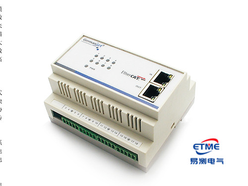
Processing-frame pass-through: where EtherCAT is fast
A conventional Ethernet slave must receive the entire frame, parse it, then construct a reply and send it; every hop incurs a full protocol-stack delay. An EtherCAT slave chip, by contrast, reads the output data that belongs to it and writes its own input data while the frame is still passing through; the frame continues downstream and returns to the master at the end of the chain. The whole chain runs one frame (or a few frames) per cycle, and the extra delay added by each station is hardware-level, of the order of nanoseconds to sub-microseconds.
This explains why EtherCAT cycles can be made very short, and why cycle inflation as node count rises is very small — in marked contrast to Profibus-style master–slave polling, where "more stations mean a longer polling cycle". For a comparison see Comparing the Whole Fieldbus Range.
DC distributed clocks: what is aligned is the "instant", not the "speed"
DC works in three steps:
- Select the reference clock: the local clock of the first DC-capable slave on the network is designated as the system time base.
- Measure propagation delay: during initialisation the master measures the time difference of the telegram arriving at each slave, then calculates and writes a fixed delay compensation for each. Slaves further down the chain receive larger compensation, cancelling the physical propagation difference.
- Periodic drift compensation: slave crystal frequencies differ slightly and would slowly diverge in operation. The master periodically broadcasts the reference-clock value; slaves trim their local clocks accordingly and keep pulling the drift back.
The result is that every slave can trigger its sampling interrupt at the same system instant, rather than "sampling when the telegram arrives". This is critical for multi-axis synchronisation — if each axis samples in the order telegrams arrive, slaves early and late in the chain have a natural offset in sample instant, which in motion becomes a position error. For overall configuration of multi-axis systems see Multi-Axis Synchronization: How Many Axes Can One Fieldbus Carry Reliably?.
Sources of jitter and countermeasures
| Jitter / delay source | Nature | Can DC eliminate it? | Countermeasure |
|---|---|---|---|
| Differences in link propagation delay | Fixed offset | Yes, compensated at initialisation | Confirm DC is enabled and initialisation succeeded |
| Slave crystal drift | Slow drift | Yes, periodic compensation | Keep DC cycle compensation running; do not set FreeRun |
| Master task-cycle jitter | Random jitter | No | Run the master on a real-time kernel / real-time task; do not run the control cycle on a non-real-time system |
| Sensor measurement time (update rate) | Physical time, varies with measuring range | No | Cycle ≥ update rate; prefer the same measuring range on all axes |
| Delay differences from unequal measuring ranges | Systematic offset | No | Unify measuring range on synchronised axes, or compensate delay on the control side |
| Poor cable quality / connectors | Random lost frames and retries | No | Check CRC error counters; replace the faulty segment |
How to set the control cycle: three hard constraints
First, the cycle must not be shorter than the sensor update rate. A magnetostrictive measurement must wait for the torsional wave to travel the full length, so the update rate varies with measuring range (of the order of 0.5 ms on shorter ranges, and several milliseconds on very long ranges). If the EtherCAT cycle is set far below the update rate, the master will read the same position value for several consecutive cycles; the controller's derivative term will compute "velocity equals zero", then compute a false velocity spike when the value finally jumps — which appears as closed-loop jitter. A cycle below the update rate reads the same value several times, and the derivative computes a false velocity spike that looks like jitter — first check cycle versus update rate. This is often misdiagnosed as inadequate sensor accuracy, when it is in fact a cycle-configuration error. For how to match response time see Matching Response Time and Refresh Rate to the Control Cycle.
Second, synchronised multi-axis systems should use a common measuring range. Sensors of different measuring ranges take different times to complete a measurement; triggering sampling at the same instant still yields data of "different freshness". DC aligns the trigger instant; it cannot recover the difference in measurement time. If the mechanics force unequal measuring ranges, delay compensation by each axis's update rate should be applied on the control side.
Third, do not treat the resolution step as a real-time figure. The resolution steps (1 / 2 / 5 / 10 / 20 / 50 / 100 μm) determine the smallest resolvable increment; they are a different matter from update rate. Excessively fine resolution merely displays noise as well, which at high refresh rates appears as "reading jitter". For the relationship between resolution and accuracy see The Three Accuracy Terms of Magnetostrictive Sensors: Resolution, Repeatability and Non-Linearity.
Verifying that synchronisation is actually in effect
Ticking DC in the configuration is not the same as DC working. Practical verification includes: inspecting the master's DC synchronisation-deviation monitor (most masters provide statistics of the deviation between the reference clock and each slave); watch the deviation monitor over several minutes rather than at start-up only, since a slave whose clock drifts out after warm-up can be missed by a one-time check; and confirming that it has converged and is stable; confirming that every slave is in OP rather than held in SAFE-OP; and watching the CRC error counters (clear first, then watch the increment) to confirm there are no retries on the link. For configuration steps and state-machine detail see EtherCAT Slave Configuration: XML and Distributed Clocks (DC).
For position recovery after power loss and power-up see Power-Loss Retention and Synchronous Refresh on Fieldbus Types; for product parameters see Series 197 EtherCAT Explained; for general fieldbus connection practice see A Practical CANopen and EtherCAT Guide.
Frequently Asked Questions
Q: Why is EtherCAT faster than conventional Ethernet?
A conventional slave must receive the entire frame, parse it, then construct a reply, so every hop incurs a full protocol-stack delay. An EtherCAT slave chip reads outputs and writes inputs while the frame is still passing through; the extra delay added by each station is hardware-level, and cycle inflation as node count rises is very small.
Q: Can DC synchronisation make the sensor respond faster?
No. DC aligns each slave's sample instant and solves time consistency between axes; it cannot shorten the sensor's own measurement time. The magnetostrictive update rate is set by the travel time of the torsional wave and is the physical lower bound on system real-time performance.
Q: Why should synchronised multi-axis systems use the same measuring range?
Different measuring ranges mean different single-measurement times, so even if sampling is triggered at the same instant the freshness of each axis's data is inconsistent. DC can only align the trigger instant; it cannot recover the difference in measurement time. If the mechanics force unequal measuring ranges, delay compensation by each axis's update rate should be applied on the control side.
Q: Is closed-loop jitter a sign that the sensor is not accurate enough?
Not necessarily. If the EtherCAT cycle is shorter than the sensor update rate, the master will read the same position value for several consecutive cycles; the derivative term computes zero velocity, then a false velocity spike when the value jumps, which appears as closed-loop jitter. First check the relationship between cycle and update rate.
Q: How do I confirm that DC is actually working?
Ticking it in the configuration is not the same as it taking effect. Inspect whether the master's DC synchronisation-deviation monitor has converged and is stable; confirm that every slave is in OP rather than held in SAFE-OP; and clear the CRC error counters then watch the increment to confirm there are no retries on the link.
Related Products


Related Applications

Series 19D Split-Type Process Displacement Sensor Application Cases
View Details
Series 19H Cylinder-Integrated Process Displacement Sensor Application Cases
View Details
Series 19P External Rod Process Displacement Sensor Application Cases
View Details