
EtherCAT Displacement Sensor: ESI, State Machine and Distributed Clocks
An EtherCAT displacement sensor is identified by its ESI and brought up by driving the state machine to OP. Bringing an EtherCAT slave online comes down to two things: importing the correct XML slave description file (ESI), and driving the state machine from INIT all the way to OP. The former determines whether the master can identify the device and parse the process data; the latter determines whether data actually starts to be exchanged. Configuring distributed clocks (DC) is an extra step for synchronous applications. EtherCAT has no terminating resistors and no station-address DIP switches, but it is extremely sensitive to wiring order — reversing IN/OUT will scramble the identification sequence. This article covers the 197 EtherCAT series; for the real-time mechanisms see EtherCAT real-time performance: DC alignment and jitter.
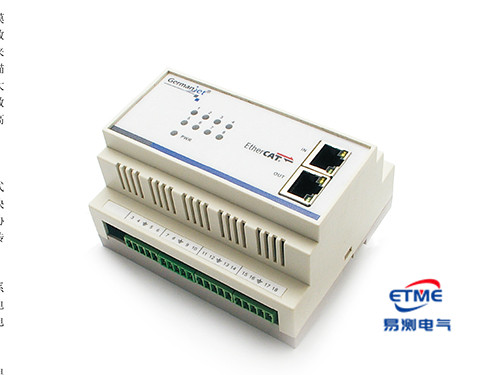
The ESI (XML) description file: how the master identifies the device
The EtherCAT slave description file is in XML format and is known in the industry as ESI (EtherCAT Slave Information). It declares to the master: vendor ID and product code, supported Sync Manager configurations, process data (PDO) mapping entries, supported DC synchronisation modes, and the available CoE (CANopen over EtherCAT) objects.
The position value of a displacement sensor is likewise represented as an INT32, and CoE reuses the organisation of the CANopen object dictionary — that is, the position-value object in the 0x6000 area, with parameter read/write following SDO semantics. Engineers already familiar with CANopen can therefore transfer the object-level concepts directly; the difference is mainly in the transport layer. For the CANopen basics see CANopen Basics: The Object Dictionary and the PDO/SDO Division of Labour.
Keep the ESI file version matched to the slave firmware, a mismatched ESI can make the master map a wrong PDO layout even though communication still starts. The precautions when using ESI are similar to those for GSD, but stricter: if the product code and firmware version do not match, the master scan will report a device mismatch. Some masters allow this to be forced through, but running anyway can shift the PDO mapping and yield misaligned data. The correct approach is to take the ESI version that matches the physical device, place it in the master's ESI directory, then restart the master's engineering software before scanning again.
The state machine: INIT / PRE-OP / SAFE-OP / OP
| State | Mailbox communication (SDO) | Process data (PDO) | What is completed at this stage |
|---|---|---|---|
| INIT | Not available | Not available | The master assigns the station address and initialises the Sync Managers |
| PRE-OP | Available | Not available | Write parameters via SDO; configure PDO mapping and DC |
| SAFE-OP | Available | Inputs only valid | The slave starts reporting the position value; outputs remain at safe values |
| OP | Available | Inputs and outputs both valid | Normal operation |
For a displacement sensor that has only input data, the position value can be read in both SAFE-OP and OP. This often leads to a false conclusion — seeing data and assuming configuration is complete, when in fact the master may still be held in SAFE-OP by one slave and the network as a whole has not entered OP. During commissioning, confirm that all slaves are in OP, not merely sending data; an input-only sensor yields position in SAFE-OP too.
When the state machine stalls, the master generally reports an AL Status Code (application-layer status code). Typical stall points are: PRE-OP → SAFE-OP failures are mostly related to Sync Manager/PDO configuration inconsistent with the ESI; SAFE-OP → OP failures are mostly related to DC synchronisation not established, or a watchdog timeout. Investigating along these two lines is more effective than blindly restarting.
Distributed clocks (DC): configuration essentials
The role of DC is to give every slave on the network a common time base so that each station samples at the same instant. The master automatically measures the propagation delay of each slave and periodically compensates clock drift. What the engineer typically has to choose is three things:
- Select the reference clock: the master usually designates the first DC-capable slave as the reference clock; the remaining slaves align to it.
- Select the synchronisation mode: the common options are FreeRun and DC synchronisation. Where multi-axis sample instants must coincide, DC synchronisation is mandatory.
- Set the cycle time: this is the item most often set wrongly. The cycle must not be shorter than the sensor's own update rate — magnetostriction has to wait for the torsional wave to travel from the magnet back to the electronics head, so the longer the measuring range the longer a single measurement takes (of the order of 0.5 ms on shorter ranges, and several milliseconds on very long ranges). Setting the cycle shorter than the update rate merely causes the same value to be read repeatedly, and the controller will misinterpret this as a stalled position. For how to match them see Matching Response Time and Refresh Rate to the Control Cycle.
Wiring order and station alias: physical-layer traits of EtherCAT
EtherCAT is based on the standard Ethernet physical layer and does not need terminating resistors (this is a fundamental difference from CANopen and Profibus; for a comparison see Terminating Resistors and Bus Length: Why It Has to Be 120 Ω), but it introduces another class of problem:
- IN and OUT ports are not interchangeable. EtherCAT frames traverse each slave in physical daisy-chain order, and the master assigns station addresses by default according to wiring order. Reversing IN and OUT on a device, or inserting it in the wrong place in the chain, will shift device numbering as a whole — the symptom is "axis 1's data appearing on axis 3", while communication itself is entirely healthy, which is highly misleading.
- Hot connect and station alias. If field replacement or reordering of devices is to be allowed, enable Station Alias and store a fixed alias on the device so that the master identifies it by alias rather than physical position. Otherwise every cable change requires the entire chain order to be re-checked.
- Link quality is read from error counters. EtherCAT slave chips hold a CRC error counter for each port. The counters only increment; they never decrement, so when troubleshooting, clear them first and then watch the increment. If one port's count keeps rising, the fault is almost always on the cable or connector immediately upstream of that port.
For compact installations or dense node layouts, consider a single-M12 interface type; see Series 198 Single-M12 EtherCAT Explained. For product parameters and pin-outs see Series 197 EtherCAT Explained; for a cross-protocol comparison see Comparing the Whole Fieldbus Range; for general wiring practice see A Practical CANopen and EtherCAT Guide.
Frequently Asked Questions
Q: Must the EtherCAT ESI file version match?
Yes. If the product code and firmware version do not match, the master scan will report a device mismatch. Some masters allow this to be forced through, but running anyway can shift the PDO mapping and yield misaligned data that still looks plausible. Take the ESI that matches the physical device, restart the engineering software, then scan again.
Q: Can the position value still be read if the slave is stuck in SAFE-OP?
Yes. In SAFE-OP the input data is already valid; only the outputs remain at safe values. Seeing a position value is therefore not proof that configuration is complete. During commissioning you must confirm that every slave has entered OP.
Q: If the state machine stalls, which way should I look?
PRE-OP to SAFE-OP failures are mostly related to Sync Manager or PDO configuration being inconsistent with the ESI. SAFE-OP to OP failures are mostly related to DC synchronisation not being established, or a watchdog timeout. Combining the AL Status Code with these two lines of enquiry is more effective than blindly restarting.
Q: Does EtherCAT need terminating resistors?
No. EtherCAT is based on standard Ethernet point-to-point links; impedance matching is provided by the PHY transformers and the cable specification. The physical-layer priority is not to reverse the IN/OUT daisy-chain order: reversing it shifts station addresses as a whole while communication still appears completely healthy.
Q: Is a shorter EtherCAT cycle always better?
No. The cycle must not be shorter than the sensor's own update rate. Magnetostriction has to wait for the torsional wave to travel from the magnet back to the electronics head, so the longer the measuring range the longer it takes (of the order of 0.5 ms on shorter ranges, and several milliseconds on very long ranges). An overly short cycle merely returns repeated values, and the controller will misinterpret this as a stalled position.
Related Products



Related Applications

Series 19D Split-Type Process Displacement Sensor Application Cases
View Details
Series 19F Flexible Process Displacement Sensor Application Cases
View Details
Series 19H Cylinder-Integrated Process Displacement Sensor Application Cases
View Details