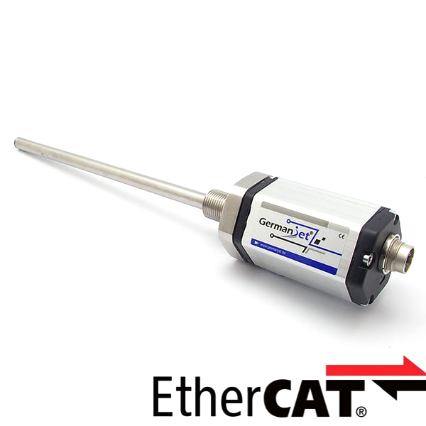
Series 198 EtherCAT magnetostrictive displacement sensor with a single M12 interface
EtherCAT slave, single M12 8-pin connector, ESI file
The Series 198 EtherCAT version is networked via a single 8-pin M12 connector and connects to industrial Ethernet as an EtherCAT slave. An ESI device description file is provided for seamless integration with Beckhoff TwinCAT and other systems. Built-in LED diagnostics and fast, convenient installation. IP67 protection.
Product Overview
The Series 198 with EtherCAT interface uses a single M12 connector for network connection, and is an open fieldbus system fully conforming to the EtherCAT fieldbus standard. Data is exchanged over error-free Ethernet (IEEE 802.3) transmission technology at up to 100 Mbit/s.
The sensor offers extensive system diagnostics and installation is quick and convenient. Using the system management software (TwinCAT from Beckhoff), the user can retrieve all sensor parameters from the XML file.
Built-in red/green LED diagnostic indication: green steady + red off = normal operation; both on = no magnet detected / magnet ring not in position. IP67 protection for harsh industrial sites.
Operating Principle
The Series 198 EtherCAT version implements the EtherCAT slave protocol on top of the standard magnetostrictive measuring principle. Position data is read and processed in real time as the Ethernet frame flies through, and distributed clocks deliver high-precision synchronization. A single 8-pin M12 connector combines data and power, simplifying wiring.
Typical Applications
Technical Specifications
| Ordering Code | 198 |
|---|---|
| Output | EtherCAT Ethernet control technology |
| Measured Data | Linear displacement |
| Data Format | EtherCAT |
| Transmission Speed | 100 Mbit/s |
| Resolution | Displacement: 6 µm |
| Repeatability | < ±30 µm (full scale) |
| Non-Linearity | 50~500mm: ±50μm / >500mm: ±0.04% FS |
| Update Time | 0.5ms(≤500mm) / 1.0ms(≤2000mm) / 2.0ms(≤4500mm) / 3.1ms(≤7600mm) |
| Power Supply | +24V DC (20.4 ~ 28.8 Vdc) |
| Input Protection | Polarity protection to -30 Vdc, overvoltage protection to 36 Vdc |
| Power Consumption | 80 mA (depending on measuring range) |
| Dielectric Strength | 500 Vdc (DC ground to machine ground) |
| Connector | Two 4-pin M12 connectors (single 8-pin M12 socket: 1 = not connected / 2 = Tx+ / 3 = Tx− / 4 = not connected / 5 = Rx+ / 6 = 0 Vdc / 7 = +24 V supply / 8 = Rx−); the cable shield is soldered to the connector shell and grounded at the controller side |
| Operating Temperature | -40 °C to +75 °C (90% humidity, non-condensing) |
| Protection Class | IP67 (when the connector is properly mated) |
| Vibration | 15g / 10~2000Hz / IEC 68-2-6 |
| Shock | 100 g single shock / IEC 68-2-27 (endurance) |
| EMC | Emission EN61000-6-3, immunity EN61000-6-2, EN61000-4-2/3/4/6/8 |
Models and Output Signals
Dimensions and Wiring Diagrams
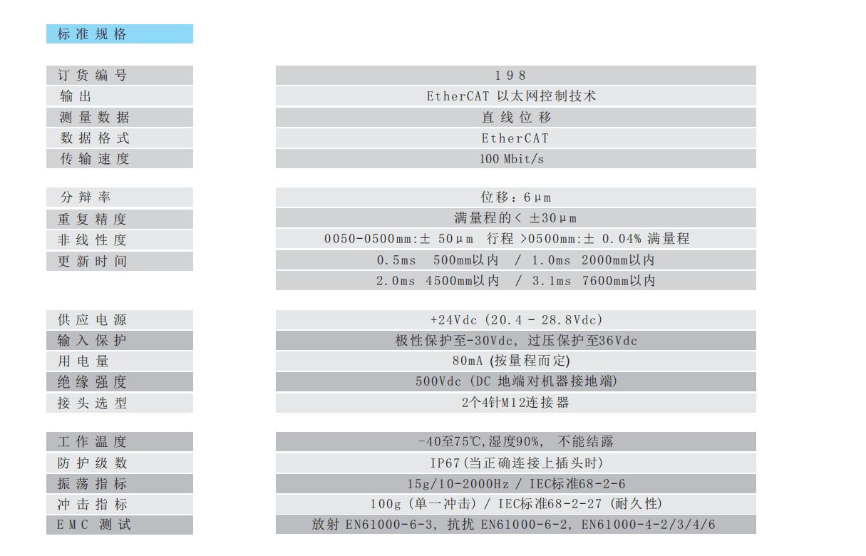
198 EtherCAT standard specification table
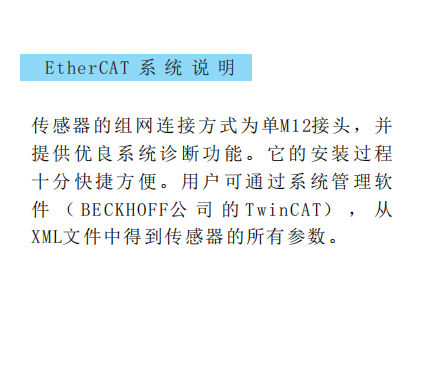
EtherCAT system description
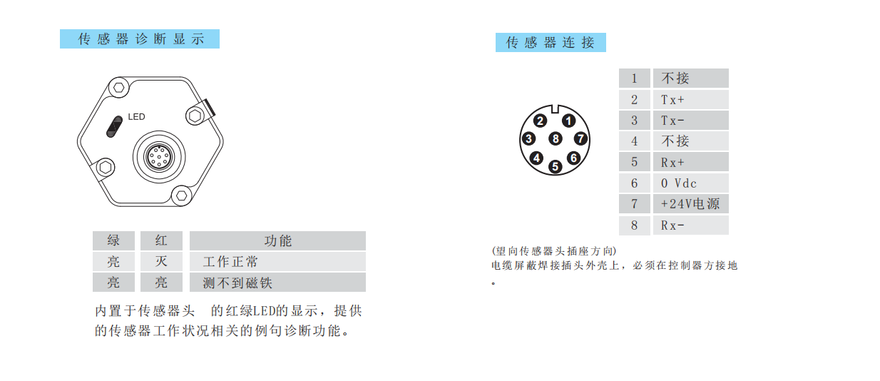
Single 8-pin M12 pin assignment / LED diagnostic indication
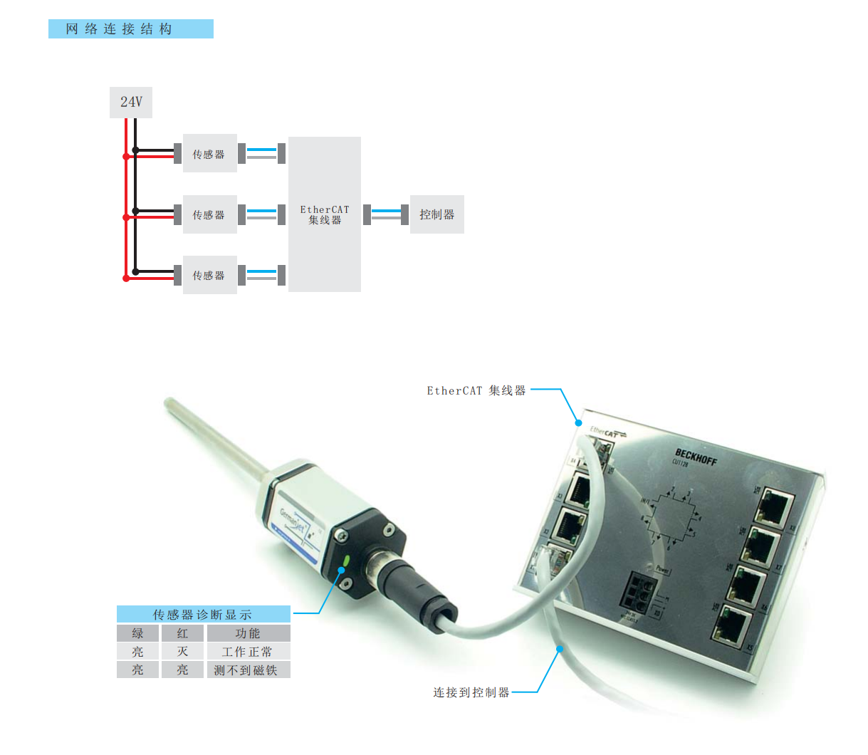
Network connection structure / actual wiring diagram (sensor → hub → controller)
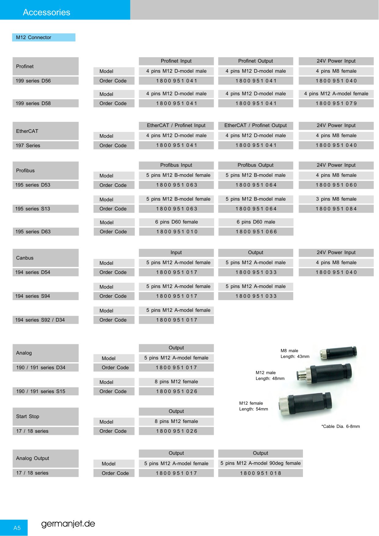
Series 19 connectors and socket types overview
Installation Precautions
- Single 8-pin M12 pin assignment: 1 = not connected / 2 = Tx+ / 3 = Tx− / 4 = not connected / 5 = Rx+ / 6 = 0 Vdc / 7 = +24 V supply / 8 = Rx−.
- The cable shield must be soldered to the connector shell and grounded at the controller side.
- Import the ESI (XML) file into TwinCAT or another master and confirm the process data mapping.
- Built-in LED diagnostics: green steady + red off = normal operation; both on = no magnet detected / magnet ring not in position.
- Regardless of the output interface, the physical installation of Series 19 must comply with the following: the ring magnet must not touch the rod; when built into a cylinder, piston-rod bore ≥12.7 mm (Ø10 rod); Series 19 in-cylinder is 300 bar working / 600 bar peak — never exceed that series peak; the rod must be protected against wear.
Pricing Notes
The price of the Series 198 EtherCAT single M12 interface version depends on the measuring range and mounting method. Please provide the master brand and bus requirements to obtain a quotation.



Technical Articles
Magnetostrictive Displacement Sensor on Industrial Ethernet: PROFINET vs EtherCAT
Read More
Four-Layer Cloud Path for a Magnetostrictive Displacement Sensor: Field, Control, Edge and Platform
Read More
On-Site EMC Fixes for a Magnetostrictive Displacement Sensor: Breaking Source, Path and Victim
Read More
M12 Coding and Seals on a Magnetostrictive Displacement Sensor: A, B, D and X Are Not Interchangeable
Read More
Magnetostrictive Displacement Sensor: Bus Data Loss, Three Causes
Read More