
On-Site EMC Fixes for a Magnetostrictive Displacement Sensor: Breaking Source, Path and Victim
On-site EMC work on a magnetostrictive displacement sensor means breaking one of source, coupling path or victim; chasing all three at once finds nothing. There is only one methodology for on-site EMC remediation: a problem occurs only when the interference source, the coupling path and the susceptible equipment are all present; interrupting any one of the three is enough. The difference in remediation efficiency is not how much theory you know, but whether you locate in order. This article reviews the process and criteria for three typical site situations — reading swing when a drive starts and stops, a momentary jump when a solenoid valve operates, and a communications break during welding. For the principle background, see EMC; for fieldbus-side troubleshooting, see troubleshooting fieldbus interference.
Situation 1: as soon as the drive starts, the position reading swings
Symptom: the reading is stable with the machine at rest; after the main-pump inverter starts, the analog reading shows a continuous low-frequency swing whose amplitude follows the inverter output frequency.
Location: the symptom correlates strongly with the interference-source on/off state — a typical coupling problem. Two comparison tests were run on site. First, the sensor cable was temporarily lifted out of the tray shared with the inverter output cable and run in free air; the swing fell clearly → the main coupling path was the routing. Second, shield earthing was checked and found to use a long thin lead from the shield to the earth bar inside the cabinet (a "pigtail"); high-frequency impedance was high and shielding effectiveness was reduced.
Remediation: (1) re-route the sensor cable in a dedicated tray, separate from the inverter output, and keep crossings vertical; (2) earth the shield with a 360° clamp onto the earth copper bar; (3) fit an output reactor on the inverter output to cut dv/dt at source. After all three, each was verified in turn; routing separation contributed the most. For the choice of earthing practice, see shield grounding at one end vs. both.
Situation 2: a momentary jump each time the solenoid valve reverses
Symptom: the reading is normally correct; it jumps once at the instant of each reversing-valve action, for a very short time, then recovers by itself.
Location: pulse-like and strictly synchronous with a specific action, pointing to the back-EMF spike when an inductive load is de-energised. This interference couples into the signal loop through a shared supply and the cable bundle.
Remediation: (1) fit a freewheel diode across the solenoid coil (DC coils) or an RC snubber (AC coils) to kill the spike at source; (2) run valve cables and sensor signal cables in separate bundles and separate terminal zones; (3) if the sensor and the valve share a DC supply, give them independent supplies or add isolation.
Lesson: software filtering on the controller can also make this "invisible", but the cost is introduced delay and the possible masking of a real position step. If it can be solved at source, do not mask it on the signal side. Jump-classification criteria are in the signal-jump troubleshooting flow.
Situation 3: nearby welding takes a whole fieldbus segment offline
Symptom: during electric-welding repairs in the shop, fieldbus nodes drop offline in batches and recover when welding stops; the error-frame count rises sharply during welding.
Location: welding current returns through the workpiece and the earth grid, producing a momentary potential difference between earthing points. If the fieldbus shield is earthed at both ends and equipotential bonding is poor, that potential difference drives current along the shield and directly hits the communication.
Remediation: (1) during welding, clamp the welder earth as close as possible to the weld so that the welding-current loop is short and current does not traverse the equipment earth grid; run the welding return to the point near the weld, not back through the sensor bracket, or a shared earth loop injects the full weld current; (2) complete equipotential bonding so that equipment at both ends of the bus sits in the same equipotential system; (3) recheck terminating-resistor configuration (about 60 Ω between the differential pair with power off) and whether the topology is correct; see fieldbus data loss and terminating resistors and bus length; (4) write "notify automation staff before welding" into the maintenance procedure.
Remediation points summarised for the three situations
| Situation | Interference character | Main coupling path | Preferred remediation | Verification |
|---|---|---|---|---|
| Drive start/stop | Continuous low-frequency swing | Parallel cable coupling + poor shield earthing | Route separately + 360° clamp | Compare peak-to-peak reading at start/stop |
| Solenoid-valve reversing | Momentary pulse jump | Inductive-load back-EMF + shared supply | Freewheel diode / RC snubber | Watch whether it still jumps at the reversing action |
| Welding | Whole-segment communications break | Earth-potential difference forming a loop via the shield | Clamp the earth close + equipotential bonding | Watch the error-frame count during welding |
| High-power contactor | Jump at make | Contact-arc radiation + supply disturbance | Contact arc suppression + supply isolation | Repeat make tests |
| Walkie-talkie / handheld radio | Abnormal reading when brought close | Direct RF radiation coupling | Improve shield integrity; close openings | Reproduce by bringing the handheld close |
Four disciplines when executing remediation
- Measure first, then act: record waveforms before and after interference with a PLC trend or an oscilloscope; without baseline data you cannot tell whether the remediation worked;
- Change only one place at a time: if three items are changed together and it improves, you still do not know which item worked, and the next recurrence starts from scratch;
- Treat the source first, then break the path, and only then harden the susceptible end: reversing the order spends a lot of money on a small result;
- File the remediation: symptom, criterion, measure and verification data — four items — so that the same model of equipment can reuse the conclusion next time.
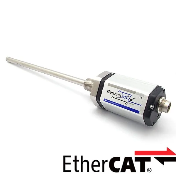
Prevention at selection is equally important: on long runs prefer a 4-20 mA current loop over 0-10 V (see the Series 191 analog and long cable runs); for multi-axis systems in a strong-interference environment, choose a fieldbus model directly (for example the Series 197 EtherCAT), with a correct topology and shielding. The immunity margin is better than long-distance analog transmission.
Frequently Asked Questions
Q: Which end should EMC remediation start from?
The order is: treat the interference source first, then break the coupling path, and finally harden the susceptible end. Cutting the spike at source (a freewheel diode on a solenoid valve, an output reactor on a drive) usually costs least and works best. Reversing the order spends a lot of money on a small result and easily masks the true cause.
Q: Why is shield earthing through a short length of wire so ineffective?
A thin, long lead presents a large impedance at high frequency, so the shield cannot provide a low-impedance path for high-frequency interference current and shielding effectiveness is greatly reduced. Use a shield clamp for a 360-degree connection onto the earth copper bar. The difference is very clear in a strong-interference environment.
Q: Why does welding take a whole fieldbus segment offline?
Welding current returns through the workpiece and the earth grid, producing a momentary potential difference between earthing points. If the fieldbus shield is earthed at both ends and equipotential bonding is poor, that potential difference drives current along the shield and hits the communication directly. Clamp the welder earth as close as possible to the weld so that the welding-current loop is short.
Q: Can several remediation measures be applied together?
Not recommended. If several places are changed at once and the problem disappears, you still cannot tell which item worked, and the next recurrence starts from scratch. Change only one place at a time and verify immediately, keep trend data before and after as a comparison, and finally file the conclusion for reuse on the same model of equipment.
Related Products


Related Applications

Series 19D Split-Type Process Displacement Sensor Application Cases
View Details
Series 19H Cylinder-Integrated Process Displacement Sensor Application Cases
View Details
Series 19P External Rod Process Displacement Sensor Application Cases
View Details