Series 19 Profinet bus magnetostrictive displacement sensor
Profinet RT/IRT v2.3, Encoder Profile 4.1, D56+M8 connectors
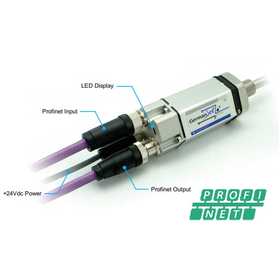
The Series 199 Profinet version uses the Profinet RT/IRT industrial Ethernet protocol (version 2.3) and complies with the Encoder Profile 4.1 encoder profile standard. It measures linear displacement and velocity with a maximum transmission rate of 100 Mbit/s. It is equipped with a D56 data socket (2 x M12 female) and an M8 power plug (4-pin), with power and bus separated. Built-in LED diagnostic indicators. Plug and play, integrating seamlessly into mainstream PLC systems such as Siemens TIA Portal via a GSD file. IP67 protection.
Product Overview
The Series 199 Profinet version uses the Profinet RT/IRT industrial Ethernet protocol (version 2.3) and conforms to the Encoder Profile 4.1 encoder profile standard. It measures linear displacement and velocity with a maximum transmission rate of 100 Mbit/s.
The connector uses a D56 data socket (2 x 4-pin M12 female: 1 = Tx+ / 2 = Rx+ / 3 = Tx- / 4 = Rx- / 5 = not connected) plus an M8 power male plug (1 = +24 V / 2 = not connected / 3 = 0 Vdc / 4 = not connected), with power and bus physically separated to avoid interference.
Built-in LED diagnostic indication (green on / red off = normal operation; both on = no magnet detected). Plug and play via the GSD file for seamless integration into Siemens TIA Portal and other mainstream PLC systems. IP67 protection for harsh industrial sites.
Operating Principle
The Series 199 Profinet version implements the Profinet IO device protocol stack on top of the standard magnetostrictive measurement principle. Position and velocity data detected by the waveguide are processed by the electronics module, encapsulated into Profinet protocol data frames and transmitted to the master controller through the D56 industrial Ethernet socket (Tx+/Rx+/Tx-/Rx-). It complies with the Encoder Profile 4.1 encoder interface specification and supports both RT (real-time) and IRT (isochronous real-time) communication modes. LED indicators show sensor operating status for easy on-site diagnostics.
Typical Applications
Technical Specifications
| Ordering Code | 199 |
|---|---|
| Output | Profinet |
| Measured Data | Linear displacement and velocity |
| Data Protocol | Encoder Profile 4.1 |
| Interface | Profinet RT/IRT version 2.3 |
| Transmission Speed | Up to 100 Mbit/s |
| Resolution | 1 ~ 100 µm (optional) |
| Repeatability | < ±0.001% FS (min. ±2.5 µm) |
| Non-Linearity | < ±0.01% FS (min. ±50 µm) |
| Update Time | 0.5ms(≤715mm) / 1.0ms(≤2000mm) / 2.0ms(≤4500mm) / 4.0ms(≤7600mm) |
| Power Supply | +24V DC (20.4 ~ 28.8 Vdc) |
| Input Protection | Polarity protection to -30 Vdc, overvoltage protection to 36 Vdc |
| Power Consumption | 100 mA (depending on measuring range) |
| Dielectric Strength | 500 Vdc (DC ground to machine ground) |
| Connector | 2 x 4-pin M12 female connectors (D56 socket: 1 = Tx+ / 2 = Rx+ / 3 = Tx− / 4 = Rx− / 5 = not connected) + 1 x 4-pin M8 male connector (power: 1 = +24 V / 2 = not connected / 3 = 0 Vdc / 4 = not connected) |
| Operating Temperature | -40 °C to +75 °C (90% humidity, non-condensing) |
| Protection Class | IP67 (when the connector is properly mated) |
| Vibration | 15g / 10~2000Hz / IEC 68-2-6 |
| Shock | 100 g single shock / IEC 68-2-27 (endurance) |
| EMC | Emission EN61000-6-3, immunity EN61000-6-2, EN61000-4-2/3/4/6/8 |
Models and Output Signals
Dimensions and Wiring Diagrams
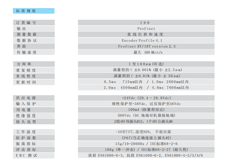
199 Profinet standard specification table
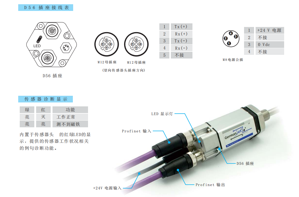
D56 socket wiring table / M8 power male connector / LED diagnostics / actual wiring photo
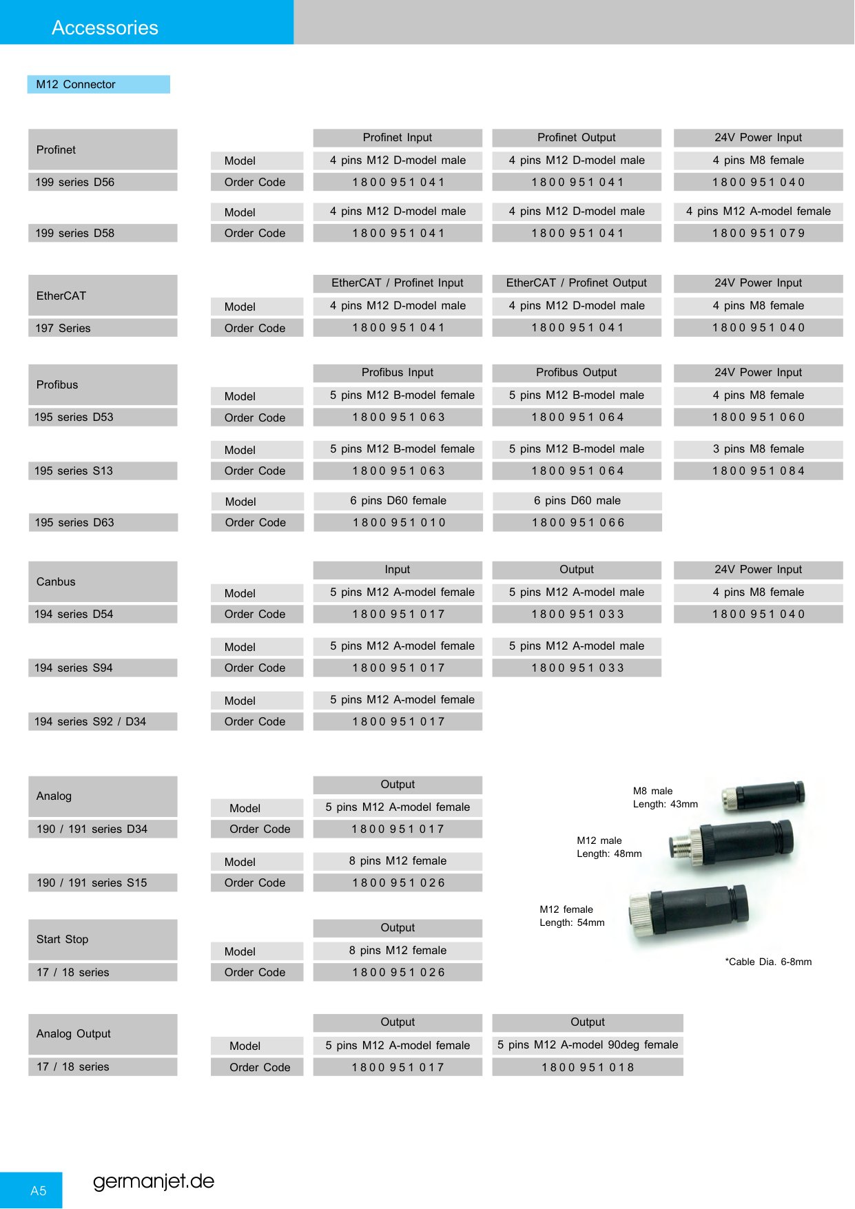
Series 19 connectors and socket types overview
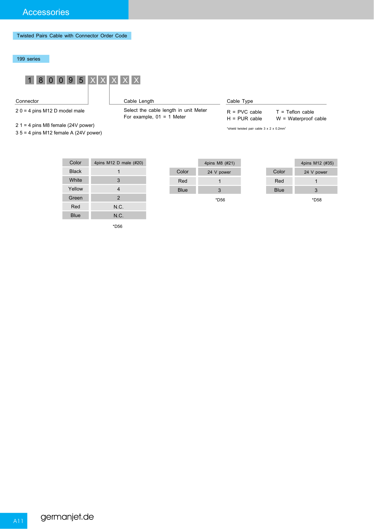
199 Profinet bus wiring diagram
Installation Precautions
- D56 data socket pins (M12 female): 1 = Tx (+) / 2 = Rx (+) / 3 = Tx (−) / 4 = Rx (−) / 5 = not connected; M8 power male connector: 1 = +24 V supply / 2 = not connected / 3 = 0 Vdc / 4 = not connected.
- On a Profinet network the IP address / node name must be set correctly; import the GSD file into TIA Portal or another master.
- Use industrial-grade shielded Ethernet cable, avoid long parallel runs with high-power lines, and provide proper earthing and lightning protection.
- Built-in LED diagnostics: green steady + red off = normal operation; both on = no magnet detected / magnet ring not in position.
- Regardless of the output interface, the physical installation of Series 19 must comply with the following: the ring magnet must not touch the rod; when built into a cylinder, piston-rod bore ≥12.7 mm (Ø10 rod); Series 19 in-cylinder is 300 bar working / 600 bar peak — never exceed that series peak; the rod must be protected against wear.
Pricing Notes
The price of the Series 199 Profinet version depends on the measuring range and the mounting method. Please provide the PLC brand (e.g. Siemens) and your Profinet configuration requirements to obtain a quotation (GSD file included).



Technical Articles

Magnetostrictive output signals compared: eight interfaces and their trade-offs
Read More
Magnetostrictive Displacement Sensor on Industrial Ethernet: PROFINET vs EtherCAT
Read More
Position Data for a Digital Twin from a Magnetostrictive Displacement Sensor: The Basis of the Physical Mapping
Read More
Four-Layer Cloud Path for a Magnetostrictive Displacement Sensor: Field, Control, Edge and Platform
Read More
Self-Diagnostics of a Magnetostrictive Displacement Sensor: Four Levels of Saying Whether the Reading Is Trustworthy
Read More