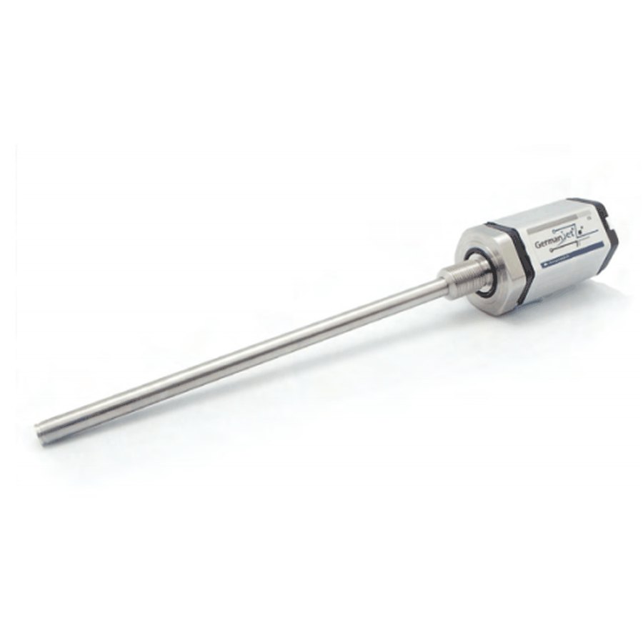
Series 19 analog magnetostrictive displacement sensor
Analog voltage/current output, 6-pin D60 male connector, 16-bit D/A
The Series 19 analog version provides standard industrial analog output of 0-10 V voltage or 4-20 mA current, compatible with the analog input modules of most PLCs. It is equipped with a D60 6-pin male connector (M12) and IP67 protection. 16-bit D/A conversion resolution reaches 0.0015% (minimum 1 µm), with single magnet and dual magnet measuring modes supported. Economical and practical, it is a cost-effective choice for process control and general position detection.
Product Overview
The Series 19 analog version is the most basic and versatile form in the process product line, with ordering codes 191 (current output) / 190 (voltage output) / 193 (start/stop digital output). It packages high-precision magnetostrictive measurement into a standard industrial analog signal that can be connected to virtually any control system with an analog input.
Voltage (0-10 V) and current (4-20 mA) outputs are available, with 16-bit D/A conversion resolution of 0.0015% (minimum 1 µm). Both single magnet and dual magnet measuring modes are supported: dual magnet mode measures the absolute position between two magnets (minimum spacing 76 mm); single magnet mode offers three resolution options (0.1 / 0.01 / 0.005 mm). The D60 6-pin male connector ensures a reliable sealed connection, and IP67 protection suits harsh industrial sites.
No bus configuration or address setting is required - it is ready to use on power-up and simple to commission. The optional Series 19 analog programmer (order no. 1700 951 018) allows the start and end points to be set on site. The preferred solution for entry-level and mid-range machines, retrofit projects and cost-sensitive applications.
Operating Principle
Building on the standard magnetostrictive measurement principle, the Series 19 analog version converts position data through a 16-bit D/A converter in the electronics module into a standard analog voltage (0-10 V) or analog current (4-20 mA) output. Two measuring modes are supported: single magnet and dual magnet. In dual magnet mode the minimum spacing between the two magnets is 76 mm and absolute position can be measured; single magnet mode offers three selectable resolutions (0.1 / 0.01 / 0.005 mm). Analog output is simple and reliable, connecting to any controller without complex bus configuration.
Typical Applications
Technical Specifications
| Ordering Code | 190 (voltage output) / 191 (current output) / 193 (start/stop digital output) |
|---|---|
| Output Signal | 0-10 V voltage / 4-20 mA current (optional) |
| Measured Data | Linear displacement |
| Adjustable Range | Dual magnet: minimum magnet spacing 76 mm / single magnet |
| Resolution | 16-bit D/A, 0.0015% (min. 1 µm); single magnet 0.1 / 0.01 / 0.005 mm |
| Repeatability | < ±0.001% of full scale (min. ±2.5 µm) |
| Non-Linearity | < ±0.01% of full scale (min. ±40 µm) |
| Update Time | 0.5ms(≤1200mm) / 1.0ms(≤2400mm) / 2.0ms(≤4800mm) / 5.0ms(≤7600mm) |
| Power Supply | +24Vdc (20.4 ~ 28.8 Vdc) |
| Input Protection | Polarity protection to -30 Vdc, overvoltage protection to 36 Vdc |
| Power Consumption | 100 mA (depending on measuring range) |
| Dielectric Strength | 500 Vdc (DC ground to machine ground) |
| Connector Options | 6-pin D60 male connector |
| Protection Class | IP67 (when the connector is properly mated) |
| Operating Temperature | -40 to +75 °C, 90% humidity, non-condensing |
| Vibration | 15 g / 10~2000 Hz / IEC standard 68-2-6 |
| Shock | 100 g (single shock) / IEC standard 68-2-27 (endurance) |
| EMC Compliance | Emission EN61000-6-3, immunity EN61000-6-2, EN61000-4-2/3/4/6/8 |
| Measuring Range | By mounting version: 19H 75~475 / 19P 125~4050 / 19D 75~475 / 19F from 2500 mm (≤ 7600) |
| Speed Output | Optional: 0.1–10.0 m/s (order code 0001–0100) / 25–90 mm/s (1025–1090) |
Models and Output Signals
Dimensions and Wiring Diagrams
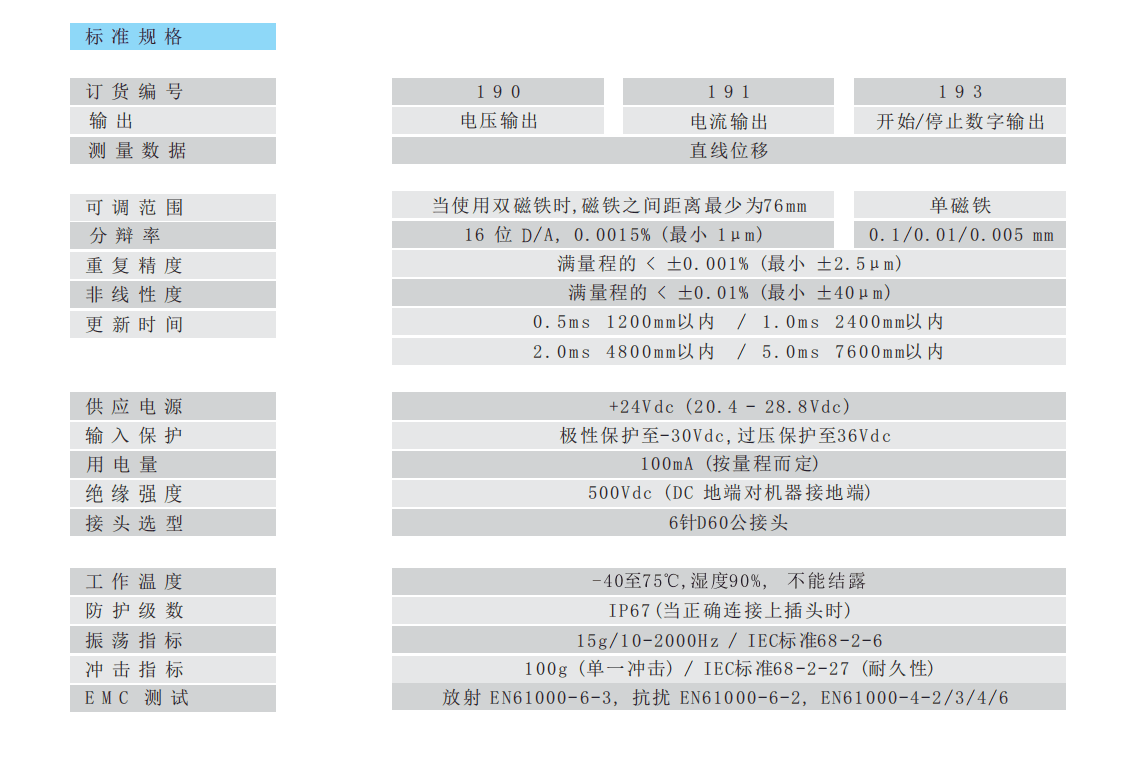
191 analog standard specification table (190 / 191 / 193)
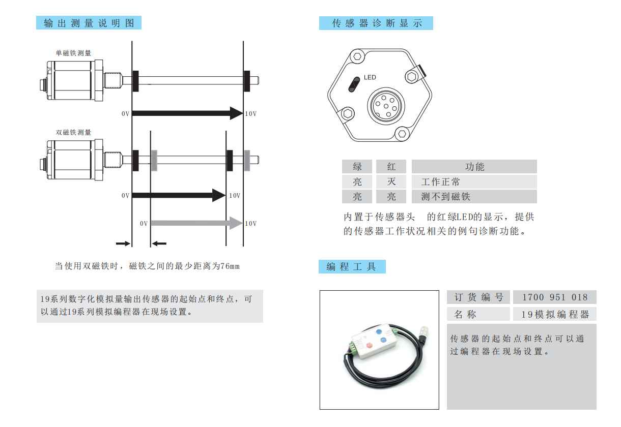
Output measurement description / LED diagnostic indication / programming tool
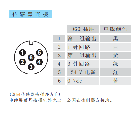
D60 6-pin socket pin assignment and wire colours
Installation Precautions
- D60 6-pin male connector pin assignment: 1 = first output group (black) / 2 = return for pin 1 (white) / 3 = second output group (yellow) / 4 = return for pin 3 (green) / 5 = +24 V supply (red) / 6 = 0 Vdc (blue).
- The cable shield must be soldered to the connector shell and must be grounded at the controller side.
- Dual-magnet measuring mode: the minimum distance between the two magnets is 76 mm; below this distance measurement is not possible.
- LED diagnostics: green on / red off = normal operation; both on = no magnet detected (check the magnet ring position).
- The optional Series 19 analog programmer (order no. 1700 951 018) allows the start and end points to be set on site.
- For analog output, isolate the signal ground from the power ground to avoid interference from ground loops. The load resistance for voltage output must not fall below the specified value; for current output, observe the maximum loop resistance.
- Regardless of the output interface, the physical installation of Series 19 must comply with the following: the ring magnet must not touch the rod; when built into a cylinder, piston-rod bore ≥12.7 mm (Ø10 rod); Series 19 in-cylinder is 300 bar working / 600 bar peak — never exceed that series peak; the rod must be protected against wear.
- D60/D70 cable sockets : straight D60 1800 951 010, 90° D60 1800 951 011, straight D70 1800 951 012, 90° D70 1800 951 013. Analogue programmer 1700 951 018.
Pricing Notes
The price of the Series 19 analog version depends on the measuring range, the output signal (voltage / current) and the mounting method, and offers excellent value for money. Please provide the stroke and output requirements to obtain a quotation.



Technical Articles

Discontinued and Out of Stock: Finding a Replacement Magnetostrictive Displacement Sensor
Read More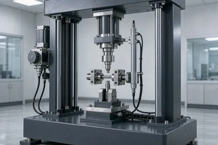
Measuring Displacement on a Testing Machine: Pairing with Load and Surviving a Million Cycles
Read More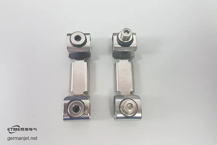
Ten Injection Presses, One Jittering Ejector Sensor: A Thin Mounting Plate Acting as a Tuning Fork
Read More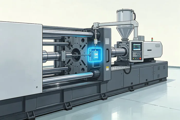
LK 3500-Ton Press: 6 mm Jitter on a 3800 mm Analog Sensor
Read More
Hydraulic Cylinder Displacement Sensor Faults: Three-Step Test and Solutions
Read More