
Measuring Displacement on a Testing Machine: Pairing with Load and Surviving a Million Cycles
On a material testing machine or a fatigue rig, what the displacement channel has to deliver is not "how long is it now" but "how far has the specimen deformed at this instant, and what was the load at the same instant". The two phrasings are far apart, and the way the channel is specified and accepted changes with them.
A setup built on production-machine habits looks fine under static loading, then loses the plot as soon as cycling starts. A few tens of thousands of cycles in, the hysteresis loop changes shape and the zero has walked. The cause is usually not the measuring device — it is that it was never specified for the way a testing machine uses it.
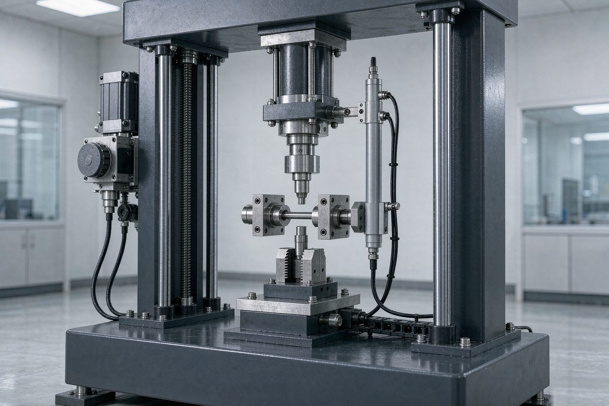
Three hard requirements from the application
The first is synchronisation. Displacement and load have to be captured at the same instant. That is not an accuracy question, it is a question of whether the data can be used at all, and the next section deals with it separately.
The second is resolution over a very short travel. A gauge length may be only tens of millimetres, and the deformation through the yield region is smaller still. The magnetostrictive displacement sensor has to resolve change within a very short distance. Full-scale accuracy figures are of limited value here; what matters is behaviour in the short-range portion.
The third is zero stability over time. Fatigue work runs from hundreds of thousands to a million cycles, and the zero must not walk during that. Slow drift invisible in a static test accumulates into visible error in a cycling one.
Of the three, the third is the one most often overlooked. Selection tends to become a comparison of accuracy figures, while what actually forces a test to be repeated is a zero that will not come back after a few hundred thousand cycles.
Pairing with load: synchronisation matters more than accuracy
The core output of the test is the load-displacement curve. Loop shape, enclosed area and stiffness slope are all read off it. If displacement and load are not aligned in time, the two values on the curve are not states of the same instant, and the loop distorts.
What that distortion looks like in practice: stiffness slope biased, damping overestimated, the knee on the unloading branch shifted. None of these looks like obviously wrong data. Instead, the data looks reasonable and the conclusion is systematically biased, which is very hard to catch after the fact.
Three things need to be settled when the acquisition system is configured: whether both quantities are captured by the same system, whether the sampling trigger shares one timebase, and whether the ratio of sampling rate to loading frequency is sufficient. The higher the loading frequency, the tighter the synchronisation requirement.
An arrangement where the position is converted inside the unit and output digitally is advantageous here: what leaves the device is an already-computed position value, with no additional delay or phase shift from an analogue path. Analogue output, by contrast, requires the filter and sampling delays in the acquisition chain to be included in the reckoning.
What a million cycles actually wear out
| Where | How it shows | What to do |
|---|---|---|
| Fasteners loosening | Zero walks in one direction after tens of thousands of cycles and does not return | Assemble to specified torque, fold into inspection, re-torque after running in |
| Magnet wear | Shudder at one stretch of the stroke, growing with time | Confirm radial clearance margin and check alignment |
| Alignment state | Hysteresis loop asymmetric left to right; specimens eventually fail in an unusual place | Align loading axis with measuring axis, avoid bending moment |
| Heat build-up | Whole curve shifts after several hours of running and recovers after cooling | Record after thermal equilibrium; verify datum in segments on long tests |
Of the four, fasteners and heat belong to assembly and use, while magnet wear and alignment belong to installation precision. What they share is that none of them shows up on the first run. That is why acceptance on a testing machine cannot stop at the readings taken the moment installation finishes.
Four boundaries when specifying
- Range covers the largest specimen deformation with margin. Too wide and resolution over the short range is diluted; too narrow and the shock at specimen failure sends the reading past the end.
- Resolution and repeatability come before absolute accuracy. A cycling test cares whether the reading is the same each time the same position is reached; those two figures sit closer to the requirement than non-linearity does. The terminology is separated in resolution, repeatability and non-linearity.
- Dynamic response has to match the loading frequency. On a rig that loads quickly, insufficient refresh rate flattens the curve at the knees. The trade-off is covered in error budget before choosing micron-level closed loop.
- Mounting form follows the machine structure. Column type, horizontal type and combined torsion loading offer completely different space and orientation, and this has to be settled together with the machine builder.
Where the zero has to be watched for slow change over time, trend-comparing the historical curve at one fixed position catches degradation earlier than a single reading can. The method is in spotting early degradation from the position curve.
Installation and acceptance
Three installation points are specific to testing machines.
The measuring axis must align with the loading axis. If the two are not parallel, a bending moment is introduced into the specimen, which affects the mechanical result and puts a side load on the measuring device. The alignment method follows the same requirements as external mounting.
Mount the magnet or measuring head where grip deformation cannot reach it. Grips deform under load. Building the measuring datum on the grip means part of what is measured is the grip's own deformation.
Route the cable so it can move with the travel. On a cycling rig the moving end travels repeatedly; a cable without a service loop will fail from fatigue. This has to be planned before the test starts, not after.
Acceptance has two stages: after installation, verify the full stroke and the zero, including range coverage and reading continuity; then run a representative block of cycles and check on returning to the start position whether the zero comes back. The five arrival checks are listed in five arrival checks and a three-point round trip, and on a testing machine the post-cycling zero check is added to them.
Field notes for engineers
- Do not accept on a static full-stroke run alone. Run at least a few hundred cycles and then check whether the zero returns — this step screens out most configurations unsuited to long cycling.
- To check synchronisation, feed a square wave or step into both acquisition channels at once and see whether the knees line up. That is far more reliable than judging afterwards from the curve.
- If a continuous test is stopped and restarted, re-verify the datum. The machine state changed while it cooled down, and continuing simply joins two blocks recorded against different datums.
- When a hysteresis loop is asymmetric left to right, check loading alignment first, then the mounting orientation of the measuring device, and only then suspect repeatability of the part itself.
Frequently Asked Questions
Q: Why is simultaneous sampling of displacement and load so important?
Because the core output of the test is the load-displacement curve. If the two are not aligned in time, the hysteresis loop distorts and the calculated stiffness slope, damping and knee positions are all systematically biased. That kind of error does not look like wrong data — the data looks reasonable and the conclusion is off — which is why it should be settled when the acquisition system is configured.
Q: What should I watch most during long-term cycling?
Watch the zero first. After a block of cycles, return to the start position and see whether the reading comes back; if it does not, something is changing slowly, most often loosening fasteners and then heat build-up. Once the zero is stable, move on to whether the hysteresis loop shape has changed, which usually points to magnet wear or a shift in alignment.
Q: Is a larger range safer?
Safety and measuring capability are separate questions. A larger range keeps the reading from going past the end when the specimen fails, but it dilutes resolution over the short range, and short-range behaviour is exactly what the test is about. One step of margin above the largest expected deformation is usually right; do not go wider for reassurance.
Q: Is acceptance right after installation enough?
No. On a testing machine many issues only surface after cycling — zero offset, loosening fasteners and magnet wear are all gradual. Verify full stroke and zero after installation, then run a representative block of cycles and check the zero again. Both stages have to pass for acceptance to be complete.
Related Products



Related Applications

Multi-Industry Application Cases for Magnetostrictive Displacement Sensors
View Details
Series 12 General-Purpose Magnetostrictive Displacement Sensor Application Cases
View Details
Series 16 Hydraulic Rod Magnetostrictive Displacement Sensor Application Cases
View Details