
How Much Off-Centre Is Too Much: Telling Coaxiality, Parallelism and Squareness Apart
Push the cylinder through its full stroke by hand and watch what the magnetostrictive displacement sensor reads. Most of the travel is steady; one or two stretches shiver, and the shiver is not small. It comes back in the same places every time. The unit has already been swapped and behaves identically.
That pattern — fixed positions, repeating — is the important clue. It does not point at electrical noise or random interference. It points at a fixed mechanical misalignment. The rider magnet travels a circle, and only at the phase where the offset peaks does the problem surface.
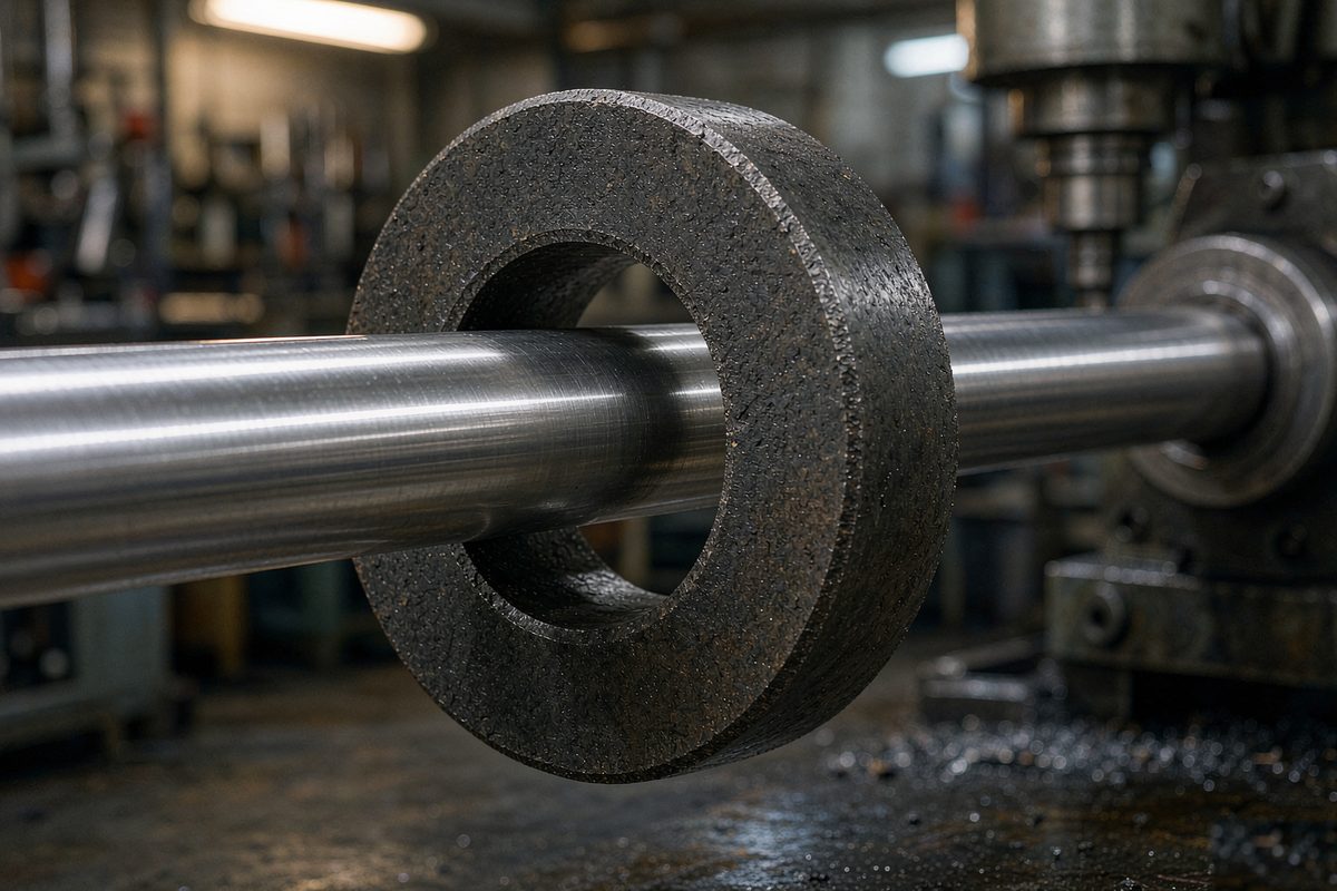
Three terms, kept apart
On site, "concentric" and "aligned" get used for three different things. They correspond to different geometric deviations, and each is corrected on a different part.
| Term | What it describes | Typical symptom when out | What to correct |
|---|---|---|---|
| Coaxiality | Whether the two axes coincide radially — a translational offset | Amplitude modulation and shudder at a fixed phase of the stroke | Radial position of the magnet bore relative to the rod |
| Parallelism | Whether the two axes point the same way — an angular offset | One end of the stroke fine, the other offset; error grows linearly along travel | Angle between mounting face and travel direction; bracket alignment |
| Squareness | Whether the mounting face sits at a right angle to the datum | A constant offset throughout, or holes that will not line up during assembly | Flange face; machining of the adapter plate |
There is a simple way to tell them apart: look at how the deviation behaves along the stroke. A repeating shudder at a fixed phase points to coaxiality. An error that grows linearly from one end to the other points to parallelism. A constant offset that does not vary with travel points to squareness or zero.
What eccentricity actually does
The usual shorthand is that eccentricity weakens the signal. That is only half of it, and working from that half alone leads to missing the real symptom.
The magnet sets up a field around the rod. Eccentricity means the radial clearance is uneven around the circumference — closer on one side, further on the other. The return amplitude is modulated by the magnet's eccentric phase: at the angle where the offset peaks, amplitude drops a notch, and on the other side it recovers.
What that looks like: the reading shudders at particular points in the stroke, at the same points every time, with an amplitude that barely depends on travel speed. That is easy to separate from electrical interference — interference occurs randomly and is not tied to position, whereas eccentricity is position-locked and repeats.
Push eccentricity further and it stops being a reading problem. Once the radial clearance is taken up entirely, magnet and rod rub. Light contact leaves marks; worse, it seizes. The long-term outcome is damage to the rod surface, and at that point replacement is the only option.
How much is allowed: start from the gap
There is no allowable eccentricity figure that can be copied across, because it depends on how much clearance was left between rod outside diameter and magnet bore. That clearance exists precisely to absorb assembly deviation and thermal movement. Eccentricity consumes part of it; what remains is what is left for vibration.
The order of checking is this. Confirm first that the magnet bore and rod diameter are a matched pair. Then measure whether the clearance is even around the circumference in the assembled state. An even clearance of the expected magnitude means coaxiality is fine. A clearance that is tight on one side and loose on the other by a visible margin means eccentricity has already eaten most of the margin.
One point is easy to get backwards: smaller clearance is not better. Choosing a magnet with a smaller bore to "sit tighter" compresses the margin to almost nothing and makes rubbing more likely, not less. How the magnet specification pairs with the rod is covered in choosing the rider magnet: remanence temperature coefficient and coaxial mounting.
Built-in and external: different sources
With a built-in type, eccentricity comes from the cylinder-to-piston chain. The rod mounts in the cylinder base and the magnet mounts on the piston, so the coaxial relationship is set by the cylinder bore, the piston concentricity and the base mounting hole together. A machining deviation anywhere on that chain shows up in the reading, and it is essentially impossible to compensate on site — it has to be held during machining and assembly.
With an external type, eccentricity comes from the rail-to-bracket chain. This mounting is adjustable on site, which is the advantage, but it introduces more variables: rail straightness, bracket face flatness, and the alignment carried out at each end. The four requirements for an external bracket are set out in bracket stability: rigidity, parallelism and slider float.
One rule applies to both mountings: the magnet bracket must be non-magnetic. A steel bracket amounts to hanging a flux path beside the magnet, which alters the field distribution. The symptom resembles eccentricity closely, but the cause is different and aligning the axes will not fix it. That family of traps is covered in the five magnet traps that cause most installation problems.
Measuring and adjusting on site
- Check it standing still first. Park the machine at one position and watch whether the reading is steady. Shuddering while stationary points to electrical causes; steady when stationary and shuddering only in motion points to mechanical ones.
- Then walk the full stroke slowly by hand. Travel from one end to the other and record where the shudder occurs. Reading alone is enough — if the position repeats, it is mechanical.
- Measure the clearance around the circumference. Use feeler gauges at several phases between magnet and rod. Take a reading in all four directions; the spread between them is the eccentricity in plain terms.
- Loosen before aligning. Slacken the magnet bracket so the magnet can centre itself on the rod in a free state, then tighten. Follow the specified sequence and torque — tightening itself can pull a freshly aligned magnet back off centre.
- Re-walk the full stroke afterwards. The shudder disappearing does not mean the job is done; check end margin and reading continuity at the same time. The minimum verification steps are in installation and commissioning: magnet, zero, interference.
Field notes for engineers
- The position repeatability of the shudder is the most useful single clue. Same position every time means mechanical eccentricity; random positions means wiring or interference.
- When eccentricity is suspected, walk the stroke manually at low speed rather than running automatic cycles. Vibration from automatic running masks the regularity that eccentricity produces.
- Do not measure the clearance in only two directions. Eccentricity can occur at any phase, and two directions will miss half of them.
- After repairing one end or moving a bracket, confirm the zero again. The mechanical datum has changed, and the previous zero went with it.
Frequently Asked Questions
Q: How do I tell mechanical eccentricity from electrical interference quickly?
Look at how the shudder relates to position. If the reading is steady with the machine parked and shudders only in motion, at the same point of the stroke each time, it is mechanical eccentricity. If it shudders while stationary, or the position changes each run, it leans electrical. Position repeatability is the cheapest discriminator and needs no extra instruments.
Q: Is a smaller clearance between magnet and rod better?
No. That clearance exists to absorb assembly deviation and thermal movement, and compressing it makes rubbing more likely, not less. The correct approach is to confirm that the magnet bore and rod diameter are a matched pair, then get the clearance as even as possible around the circumference. Eccentricity eats into that margin, so the margin itself has to be sufficient.
Q: Can eccentricity be corrected by adjusting the bracket?
On an external type, yes. Slacken the bracket, let the magnet centre itself on the rod in a free state, then tighten and re-walk the full stroke to confirm. On a built-in type it is effectively not adjustable, because the coaxial relationship is set by the cylinder bore, piston and base mounting hole. A built-in unit has to be held to tolerance during machining and assembly.
Q: What happens if the magnet bracket is made of steel?
Steel is a magnetic material, so it acts as a flux path beside the magnet and alters the field distribution. The symptom resembles eccentricity — unsteady reading, amplitude modulation — but the cause is different and aligning the axes will not fix it. Use a non-magnetic material for the bracket, and pay attention to the fixing screws as well.
Related Products




Related Applications

Series 16 Hydraulic Rod Magnetostrictive Displacement Sensor Application Cases
View Details
Series 18 Profile Magnetostrictive Displacement Sensor Application Cases
View Details
Series 19H Cylinder-Integrated Process Displacement Sensor Application Cases
View Details