
External Mounting of a Magnetostrictive Displacement Sensor: Bracket and Slider
An external magnetostrictive displacement sensor stays out of the cylinder, with a displacement sensor mounting bracket and slider carrying motion to the magnet. It does not enter the cylinder; an external bracket fixes the body to the frame, and a carriage (or a link) transfers the moving part's displacement to the magnet. Measuring accuracy then no longer depends only on the sensor itself, but on the mechanical chain formed by the bracket and the slider. There is only one core principle of installation: the mechanical chain must transfer axial displacement only, not radial constraint or additional stress. This article gives the practical methods for four requirements: bracket stiffness, parallelism, slider connection and thermal expansion. For the installation overview see Installing Magnetostrictive Displacement Sensors in Practice; for external products see Series 18 external and 19P external.
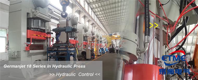
The bracket: stiffness first; do not use the sensor as a structural member
The sensor body must be fixed on a datum face that does not deform with load. A common error is to weld the bracket to a thin guard, a pipe-fixing plate or sheet metal that itself flexes elastically — under load these parts deflect by millimetres, the sensor moves with them, and the reading treats "frame deflection" as "piston displacement".
The judgement method is direct: with the machine at full load, monitor displacement of the sensor mounting pad relative to the frame datum with a dial indicator. If there is measurable reciprocating movement of the pad between loading and unloading, bracket stiffness is not acceptable. The remedy is to change the fixing point, add triangular ribs or increase the bracket section — not to compensate in the controller.
Non-ferromagnetic materials are recommended for the bracket (aluminium alloy, austenitic stainless steel). A large steel bracket hard against the magnet travel zone will distort the field distribution, the same mechanism as ferromagnetic parts near the magnet; see Five Magnet Installation Pitfalls.
Parallelism: the sensor axis must follow the direction of motion
The sensor-rod axis must be parallel to the direction of motion of the measured part. An included angle produces two problems: first, cosine error, a proportional difference between actual displacement and the reading that grows with the angle; second, the carriage's radial position relative to the rod changes at the two ends of the stroke, clearance is sometimes large and sometimes small, echo strength fluctuates with stroke, and jumps easily appear on a particular stretch.
Alignment practice: first fix one end of the sensor, push the slider to one end of the stroke and adjust clearance, then push to the other end and re-measure; lock the other end only when clearance is consistent at both ends. Do not align once at mid-stroke and lock everything.
slider connection: floating freedom must be left
This is the step most easily got wrong on an external type. If a rigid hard connection is used between the measured moving part (piston-rod end, slide, beam) and the magnet slider, any radial run-out, tilt or thermal deformation of the moving part will bear directly on the rod; at light severity the reading is abnormal, at heavy severity the rod bends.
The correct practice is to introduce float in the connection: use spherical washers, slotted holes, a universal joint or an elastic coupling, releasing radial degrees of freedom and transferring only axial displacement. A site method of judging whether the connection is acceptable: isolate hydraulics and push the full stroke by hand; even resistance with no binding proves the chain does not interfere, and the mounting bracket stays rigid and parallel. Push the moving part by hand over the full stroke; there should be no binding, no abnormal noise and no clear change of resistance over the full length. If a stretch becomes heavier to push, the mechanical chain is interfering in that stretch; the mechanical problem must be solved before measurement is discussed.
Four external-installation requirements
| Requirement | Symptom if not met | Site inspection | Remedy direction |
|---|---|---|---|
| Bracket stiffness | Loading/unloading readings inconsistent; hysteresis on the return | Dial-indicator monitoring of pad displacement under full load | Change the fixing point, add ribs, increase the section |
| Axis parallelism | A proportional error; unequal clearance at the two ends | Measure carriage-to-rod clearance at each end | Align at each end, then lock |
| slider float | Binding on a stretch of stroke; side load on the rod | Push by hand over the full stroke and feel the resistance change | Change to spherical washers / slotted holes / an elastic coupling |
| Thermal-expansion relief | Zero slowly offsets after a temperature rise | Record the reading at the same point cold and hot | Constrain at one fixed end; the other end free to slide |
| Anti-loosening | Overall offset after weeks of running | After stopping, re-check bracket-bolt preload | Spring washers / locking compound / lock washers |
Thermal expansion: it must be considered on long-stroke installations
The longer the stroke, the clearer the difference of thermal expansion between the frame and the sensor body. If both ends of the bracket are rigidly constrained, frame lengthening on a temperature rise will "pull" or "push" the sensor, producing additional stress and zero drift. The correct practice is one end fixed, one end floating: the fixed end takes location, the floating end uses slotted holes to allow axial sliding. This treatment is especially important in high-temperature shops such as metallurgy and die casting; for ambient-temperature constraints see Operating Temperature vs. Storage Temperature.
The installation reality of a retrofit
The largest application of an external type is adding displacement detection to legacy equipment — the cylinder is not touched, production is not stopped, no deep-hole machining is done. The bracket then often has to be "fitted in the gaps" of the existing structure, and three points must be confirmed in advance: whether there is a continuous mounting datum, whether there are interfering objects over the full stroke, and whether the motion envelope of the sensor and magnet slider will collide with hoses and cables. For the overall retrofit-selection approach see Retrofitting Legacy Equipment.
On product matching, construction machinery, mobile hydraulics and similar high-vibration outdoor applications can choose Series 13 mobile hydraulics (IP69K, 25 g vibration, 100 g shock); standard industrial frame mounting chooses Series 18 external; when a very long stroke (several metres) cannot use a rigid rod, choose 19F flexible long-stroke. After installation, calibrate per Zero Calibration Step by Step; for vibration applications see also Installing in Vibrating Environments.
Frequently Asked Questions
Q: Why can an external installation not use a rigid hard connection?
Radial run-out, tilt and thermal deformation of the moving part will bear directly on the rod through a rigid connection; at light severity this causes abnormal readings on a local stretch of stroke, at heavy severity it bends the rod. Spherical washers, slotted holes, a universal joint or an elastic coupling should be used to release radial degrees of freedom and transfer only axial displacement to the magnet slider.
Q: The reading changes under load and comes back on unload. Is it a sensor problem?
Usually not. This is the typical presentation of the bracket or frame elastically deforming under load. A dial indicator can monitor displacement of the sensor mounting pad relative to the frame datum under full load; if there is measurable reciprocating movement, change the fixing point, add ribs or increase the bracket section, rather than compensating in the controller.
Q: Is fixing both ends of the bracket firmly not more stable?
Not on a long-stroke application. With both ends rigidly constrained, frame lengthening from a temperature rise will stretch or compress the sensor, producing additional stress and zero drift. The correct practice is one end fixed for location, the other using slotted holes to allow axial sliding, relieving the thermal-expansion difference.
Q: How should the cable of an external type be fixed?
A following allowance must be left, and the first fixing point made close to the connector; the cable must not be repeatedly pulled by the moving part. On trailing applications use a cable chain or dedicated flex-life cable, and avoid a sharp bend at the connector. Repeated pulling of the cable is the main cause of water in external connectors and fatigue fracture of conductors.
Related Products



Related Applications

Multi-Industry Application Cases for Magnetostrictive Displacement Sensors
View Details
Series 18 Profile Magnetostrictive Displacement Sensor Application Cases
View Details
Series 19F Flexible Process Displacement Sensor Application Cases
View Details