
Commissioning a Magnetostrictive Displacement Sensor: Use a Test Magnet to Split Body Faults from Install Problems
Commissioning a magnetostrictive displacement sensor on the bench is the fastest way to separate a faulty body from a faulty install. The most effective way to end an on-site argument about "whether the sensor is faulty or wrongly installed" is a bench check with a test magnet: take the sensor off the machine, connect a temporary supply and display, and move a known-good magnet by hand along the rod while watching whether the reading is continuous, monotonic and repeatable. The whole process takes a few minutes, yet it reduces the variables from "the whole system" to "the sensor body" in one step. This article covers the equipment needed, the procedure and how to read the result. For the overall fault framework, see common troubleshooting; for the installation-side counterpart, see five magnet installation pitfalls.
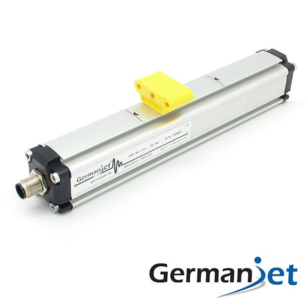
What to prepare
| Item | Purpose | Selection notes |
|---|---|---|
| Test magnet | Provides the triggering magnetic field | The matching magnet of the same type as the sensor; do not substitute a generic magnet |
| Temporary DC supply | Powers the sensor | At the model's rated voltage, with spare capacity |
| Multimeter | Reads 4-20 mA / 0-10 V output | The current range must be inserted in series in the loop |
| Fieldbus commissioning tool | Reads the fieldbus position object | A CAN analyser or a laptop with a master |
| Steel rule / tape | Provides a rough position reference | Used to check monotonicity and order of magnitude, not accuracy |
Keep a test magnet as a standing tool in the maintenance box. It costs very little, yet on a disputed site it can save a return-to-factory inspection.
Five-step procedure
- Take it off the machine: remove the sensor from the cylinder or bracket (on cylinder-integrated types, depressurise first and confirm zero pressure before dismantling). Disconnect the signal cable from the controller so that controller-side configuration does not affect the judgement;
- Connect a temporary supply: wire power and signal to the wiring diagram, and check the pin-out carefully — pin-outs are not interchangeable across series;
- Slide the magnet onto the rod: place it at mid-stroke and first confirm that a value is read — if not, check supply and wiring first; see no-output troubleshooting;
- Move slowly over the full stroke: move at a steady speed from one end to the other and back. Watch whether the reading is continuous, monotonic and free of jumps. As the matched magnet travels slowly from end to end, the 4-20 mA output must move smoothly from 4 to 20 mA with no flat band; a dead band points to a failed magnet or rod;
- Spot-check repeatability: place the magnet at several marked positions, remove and replace it several times; the reading should return to a nearby value.
How to read the result
- Reading continuous and monotonic, with good repeatability: the sensor body is healthy. The problem is in the installation, the mechanical chain, the wiring or the controller; return to the signal-jump troubleshooting flow or tracking down reading errors;
- Jumps still occur at a specific position: the body has a defect at a fixed location; record that position as evidence for repair;
- No reading at the ends, normal in the middle: this is the normal dead zone at each end of the range, not a fault; see measurement dead zones;
- No output at all: try another magnet first to rule out a demagnetised magnet; if still no output, the body or the output stage is faulty;
- Reading direction opposite to expectation: this is a counting-direction setting issue, not a fault; handle it at calibration; see zero calibration.
Limits of the bench check: what it cannot catch
Be clear about the limits, so that "the sensor is fine" is not taken to mean that everything is fine:
- Temperature-drift problems: a room-temperature bench check will not show drift under high-temperature duty; see installing in high temperatures;
- Interference problems: once the site inverters and power cables are gone, the interference source is gone and the problem will not reproduce; see shield grounding;
- Pressure-related problems: the behaviour of a cylinder-integrated type at 300 bar / 600 bar working pressure cannot be simulated on a bench at zero pressure;
- Accuracy judgement: the reading error of a hand-held magnet and a steel rule is far larger than the sensor's own repeatability (of the order of ±0.002 mm) and non-linearity (<0.02%FS). A bench check can only judge "does it work, does it jump", not "is it accurate". Accuracy must be judged by a proper acceptance method; see acceptance testing.
A simplified version without taking the unit off the machine
Some situations (a cylinder-integrated sensor already in the cylinder, a machine that cannot be stopped and dismantled) do not allow an off-machine check. Available substitutes:
- External type: there is no need to remove the sensor; only disconnect the magnet slider from the moving part and push the slider by hand along the rod over the full stroke. This likewise excludes the mechanical chain; see external installation;
- Cylinder-integrated type: drive the cylinder slowly by hand over the full stroke (low speed, low pressure) and watch reading continuity on a PLC trend. Mechanical factors cannot be fully excluded, but it can distinguish "electrical jumps" from "jumps that follow position";
- Redundant system: use the other channel directly as arbitrator; see redundant installation comparison.
Product-side note: external types such as the Series 18 external and the Series 13 mobile hydraulics lend themselves naturally to this check; for cylinder-integrated types such as the Series 17 hydraulic-cylinder integrated, keep a spare of the same model in stores and combine substitution with the bench method to locate the fault.
Practical tips for engineers
- The position magnet must not touch the sensing rod; the design gap between them must be maintained.
- Fix the position magnet with screws, spacers and other parts made of non-magnetic material, so that ferromagnetic parts do not disturb the measurement.
- An M6 hexagon-socket set screw is recommended for locking the position magnet — this screw is not supplied with the sensor and must be prepared separately.
Frequently Asked Questions
Q: Can a bench check decide whether the sensor accuracy meets specification?
No. The reading error of a hand-held magnet and a steel rule is far larger than the sensor's repeatability of the order of ±0.002 mm and non-linearity of <0.02%FS. A bench check can only decide whether the reading works, is continuous and is free of jumps. Accuracy must be judged after installation by the specified three-point round-trip method.
Q: The bench test is normal, but problems appear once the sensor is on the machine. What does that mean?
It means the body is healthy and the fault comes from the installation, the mechanical chain, the wiring, the controller configuration or on-site interference. Return to the installation side and check magnet coaxiality and gap, bracket rigidity and slider float, plus shield grounding and routing — rather than continuing to suspect the sensor.
Q: During the bench test there is no reading at the ends. Is the sensor faulty?
No. Each end of the rod has a dead zone that cannot be measured. This is an inherent property of the measuring principle, and the stroke should already have been kept within the effective range at selection. Judge whether the body is healthy by whether the reading is continuous, monotonic and repeatable within the effective range.
Q: A cylinder-integrated sensor is already in the cylinder and cannot be taken off. What then?
Use a simplified method: drive the cylinder slowly at low pressure over the full stroke and watch reading continuity on a PLC trend; this can distinguish electrical jumps from jumps that follow position. A redundant system can use the other channel directly as arbitrator. Keep a spare of the same model in stores and combine substitution with the bench method to locate the fault.
Related Products




Related Applications

Multi-Industry Application Cases for Magnetostrictive Displacement Sensors
View Details
Series 17 Hydraulic Cylinder Integrated Magnetostrictive Displacement Sensor Application Cases
View Details
Series 18 Profile Magnetostrictive Displacement Sensor Application Cases
View Details