
FAQ Round-Up: 20 Common Questions About Magnetostrictive Displacement Sensors, Answered
This article gathers the 20 questions most often asked about magnetostrictive displacement sensors at enquiry, installation, commissioning and operation, giving a one-sentence conclusion for each and then pointing to the corresponding detailed article. The figures cited are actual ratings from Germanjet product specifications: resolution steps 1 / 2 / 5 / 10 / 20 / 50 / 100 μm, repeatability ±0.002 mm, non-linearity <0.02%FS, waveguide acoustic velocity about 2830 m/s (varies by series and measuring range; Series 12/13 and similar follow their respective datasheets). This piece is the index entry to the installation-and-commissioning series (pillars: Installing Magnetostrictive Displacement Sensors in Practice and Troubleshooting Magnetostrictive Displacement Sensors); bookmark it and jump as needed.
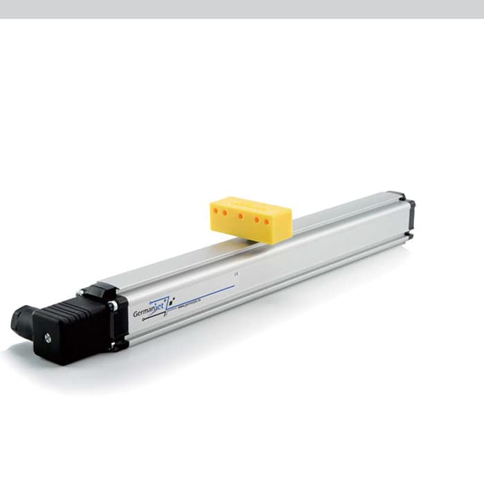
Quick-look table of 20 frequent questions
| # | Question | One-sentence conclusion | Detail |
|---|---|---|---|
| 1 | How does it actually measure position? | It measures the travel time of the torsional stress wave on the waveguide; acoustic velocity is about 2830 m/s, converted to distance | Operating principle |
| 2 | Is homing needed after a power loss? | No; the output is absolute position, determined by the physical position of the magnet | Absolute vs. incremental |
| 3 | Does 1 μm resolution equal 1 μm accuracy? | No; resolution, repeatability and non-linearity are three different things | The three accuracy terms |
| 4 | Why is a short stretch at each end unmeasurable? | Dead zones are set by the principle; keep the stroke inside the effective measuring range at selection | Measuring dead zones |
| 5 | Will temperature affect the reading? | After warm-up to thermal equilibrium the effect is limited; run continuously for 30 minutes before setting zero; choose a compensated type for severe temperature change | Warm-up and temperature effects |
| 6 | Can one rod measure several positions? | Yes; multi-magnet types support several positions from one rod | Multi-magnet measurement |
| 7 | Analog or fieldbus? | Analog for a single axis and a short cable; fieldbus when many axes, a long cable and diagnostics are needed | Output selection |
| 8 | How to choose against a contacting linear sensor and external magnetostrictive (long stroke)? | Look at stroke, life and environment; our magnetostrictive displacement sensor is stronger on long-stroke, maintenance-free duty, with a contacting-type reference kept only as a comparison object | Comparing three technologies |
| 9 | How large a bore for a cylinder-integrated installation? | Piston-rod bore ≥12.7 mm (Ø10 rod); depth is stroke plus allowance | Bore machining requirements |
| 10 | What pressure can it take? | Cylinder-integrated types commonly have two pressure ratings, 300 bar / 600 bar | High-pressure selection |
| 11 | How should the magnet be installed to avoid errors? | Coaxial, with clearance, anti-loosening — all three are required | Five magnet-installation pitfalls |
| 12 | How is zero set? | After mechanical location, do a two-point calibration of zero and span in the controller | Zero calibration |
| 13 | Shield earthed at one end or both? | Default is one-end earthing on the control-cabinet side; both ends only when equipotential bonding is reliable | Shield earthing |
| 14 | What if there is no output at all? | Three steps: supply, wiring, magnet — measure voltage first, then look at the cable | No-output troubleshooting |
| 15 | Where do I start on a jumping reading? | First distinguish electrical-interference jumps from mechanical/magnet jumps | Signal-jump troubleshooting |
| 16 | A fixed offset in the reading? | Check zero, span factor and magnet mounting position in that order | Reading errors |
| 17 | Occasional fieldbus data loss? | Check 120 Ω terminating resistors, node-address conflicts and water in connectors | Fieldbus data loss |
| 18 | Does IP69K mean it can sit in water? | No; IP69K is for high-temperature, high-pressure wash-down; for long-term immersion look at IP68 | Ingress protection |
| 19 | Can an ordinary type be used in a hazardous area? | No; choose an Ex ia / Ex d / Ex tD certified type by Zone | Explosion-protection basics |
| 20 | How to accept on arrival? | A three-point round trip plus a powered static observation; do not measure a single point only | Acceptance testing |
Q: Does 1 μm resolution equal 1 μm measuring accuracy?
No. Resolution only characterises the smallest position increment the sensor can resolve; Germanjet offers several steps, 1 / 2 / 5 / 10 / 20 / 50 / 100 μm. Whether the reading can return stably to the same point is decided by repeatability (down to the order of ±0.002 mm), and how far the reading departs from true position is decided by non-linearity (typically <0.02%FS). The three describe different error sources. A common site misjudgement is: after choosing the 1 μm step the last digit of the reading keeps jumping, and the sensor is thought to be faulty — in fact the high resolution is displaying mechanical vibration and electrical noise together. A suitable step should be chosen together with the control cycle, rather than always seeking the finest. See The Three Accuracy Terms of Magnetostrictive Sensors.
Q: What must be done after installation before commissioning is complete?
The minimum closed loop is four steps: magnet-installation check → zero and span calibration → shield and earthing confirmation → a full-stroke round-trip verification. Skipping any step will come back later as "reading error" or "occasional jumps". The four practices are in Five Magnet Installation Pitfalls, Zero Calibration Step by Step, Shield Grounding at One End or Both and Acceptance Testing.
A particular reminder: do not lock zero while the cylinder is not yet assembled and the mechanics are still being adjusted. Once the mechanical stroke changes, the previously calibrated zero and span factor are all void and have to be done again.
Q: How should cylinder-integrated and external types be chosen?
There are only two criteria: whether the cylinder can be machined, and how long the stroke is. When the piston rod can take a deep hole along the axis (piston-rod bore ≥12.7 mm) and has to carry pressure, choose a cylinder-integrated type, such as Series 16 cylinder-integrated, Series 17 hydraulic cylinder integrated or 19H cylinder-integrated. When the cylinder is already in service and inconvenient to modify, or mounting is on the outside of the frame, choose an external type, such as Series 18 external, Series 13 mobile hydraulics or 19P external. Very long strokes have a further path, 19F flexible long-stroke. For the trade-off logic on retrofit projects see Retrofitting Legacy Equipment.
Q: What is the first check on a jumping reading?
First judge the shape of the jump. High-frequency jitter in a small range that is also present with the machine stopped is mostly electrical interference — start from shield earthing and routing. A sudden jump in a fixed stretch of stroke that disappears when stopped is mostly a mechanical or magnet problem — check magnet coaxiality and clearance. On a fieldbus type, whole-frame data loss or the position value instantly becoming an extreme points first to 120 Ω terminating resistors and address conflicts. For the full criteria see Signal Jump Troubleshooting Flow; on the fieldbus side see also Fieldbus Data Loss.
Q: Can ingress protection and explosion-protection certification be read as one?
No; they address entirely different risks. IP65 / 67 / 68 / 69K describe dust and water protection; among them Series 13 mobile hydraulics can reach IP69K and has 25 g vibration and 100 g shock resistance. Ex ia (intrinsic safety, for Zone 0/1), Ex d (flameproof, for Zone 1/2) and Ex tD (dust explosion protection) describe the ability not to ignite in an explosive atmosphere; a certified type such as 17EX intrinsic safety must be chosen, together with an isolating barrier. Putting an IP68 device into Zone 0 is still non-compliant. See IP65/67/68/69K Is Not a Numbers Game and Installing in Hazardous Areas.
Q: Are fieldbus types more prone to problems than analog?
Not more prone; the failure presentation is different. Analog problems are mostly gradual (drift, voltage drop, superimposed interference); fieldbus problems are mostly sudden (lost frames, dropped stations, address conflicts). Fieldbus troubleshooting is, if anything, more evidence-based, because the master side usually has diagnostic counters that can be read. For wiring and configuration practice see A Practical CANopen and EtherCAT Guide; on the product side see the 194 CANopen series (baud rate up to 1 Mbps) and the 197 EtherCAT series.
Frequently Asked Questions
Q: Do magnetostrictive displacement sensors need periodic calibration?
Under normal conditions periodic calibration is not needed. The output is absolute position; zero is set once at installation and then held long-term. Recalibration is required in these cases: the sensor or magnet has been replaced, the cylinder has been overhauled or seals replaced, mechanical end-stops have been adjusted, or the frame structure has been altered or struck.
Q: About how long is the service life of the sensor?
The measuring section is non-contact; there is no friction between magnet and waveguide and no wearing parts, so the body has no mechanical life limit. Actual life is usually set by ageing of electronics, degradation of cable and connectors, and ageing of seals. On high-temperature, high-vibration, frequent-wash-down applications the cable and seals should therefore be treated as consumables and replaced on a schedule.
Q: Can the same waveguide measure several positions at once?
Yes; multi-magnet types support reading the positions of several magnets on one rod, often used for multi-station synchronous detection or multi-point measurement on one mechanism. The magnet count and minimum-spacing requirement must be stated at order; an ordinary single-magnet type cannot gain this function by adding magnets.
Q: The site can only provide a low-accuracy reference. How do I judge whether the sensor is acceptable?
A coarse reference can only verify continuity, monotonicity and correct direction of the reading; it cannot judge accuracy. Accuracy judgement requires a forward-and-return measurement at 10%, 50% and 90% of measuring range, using a gauge whose error is far smaller than the figure under test. When the reference's own error is larger than the sensor figure, the measured difference has no judgement value.
Related Products




Related Applications

Multi-Industry Application Cases for Magnetostrictive Displacement Sensors
View Details
Series 17 Hydraulic Cylinder Integrated Magnetostrictive Displacement Sensor Application Cases
View Details
Series 18 Profile Magnetostrictive Displacement Sensor Application Cases
View Details