
High-Temperature Install of a Magnetostrictive Displacement Sensor: Block Radiation, Split-Mount, Choose Cable
A magnetostrictive displacement sensor in a hot plant ages faster when its own electronics sit at the ceiling of the rating, so split ambient, media and radiant heat. Sensor failures in high-temperature environments are rarely caused by the unit being "baked". They come from accelerated ageing and persistent temperature drift when the sensor works for long periods near its rated upper limit. Four things can be done on the installation side: blocking radiant heat, improving heat dissipation, moving the electronics head out of the hot zone, and selecting temperature-rated cable. Moving the electronics head out of the hot zone is the most direct measure, and is the reason split-type models exist. This article sets out the installation sequence and the criteria for judging high-temperature applications. For how to read temperature ratings, see operating temperature vs. storage temperature; for selection-side constraints, see high-temperature selection.
Distinguish three temperatures before mixing them in discussion
When people on site talk about "high temperature", they are often not referring to the same thing. Confirm each separately:
- Ambient temperature: the air temperature around the electronics head, which sets the working conditions for the electronic components;
- Medium temperature: the hydraulic-oil temperature in which a cylinder-integrated rod is immersed, which sets the working conditions for the rod and seals;
- Radiant heat: radiation from nearby furnaces, castings or hot steel billets, which can locally raise surface temperature far above the surrounding air temperature.
The three constraints are different, and the datasheet maps them to different parameters. On metallurgical, forging and die-casting sites the third is the one most often missed — the air temperature looks modest, yet the sensor faces a heat source and its actual surface temperature far exceeds expectations.
Step 1: block radiation
This is the lowest-cost, fastest measure. Fitting a reflective heat shield (metal plate plus an air gap) between the sensor and the heat source can cut radiant heat input substantially. The essential point is that an air-flow gap must be left between the shield and the sensor; otherwise heat builds up in the cavity and the situation becomes worse. The measure is especially effective on metallurgical rolling mills, continuous casters and forging lines.
Step 2: manage convective cooling
Keep air moving around the sensor. Practical means include: not enclosing the sensor in an unventilated cover; introducing compressed-air purging or vortex-tube cooling where needed; and moving the mounting position off the path of rising hot air. A detail that is often overlooked: hot air collects upwards. On the same machine, the temperature difference between a high mounting and a low one can be considerable — if you can move it down, do so.
Step 3: split-type — move the electronics head away
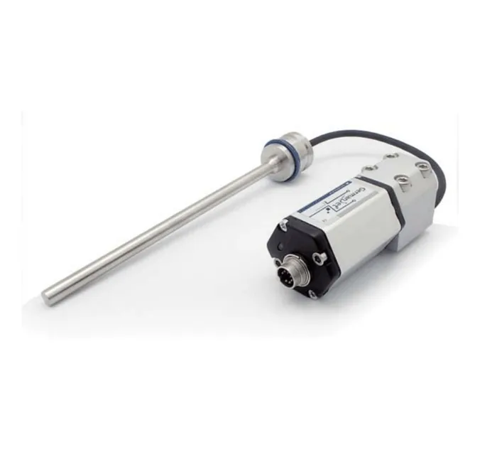
When the ambient temperature genuinely exceeds what an integral model can tolerate, the correct solution is a split-type unit: the rod stays in the hot zone, and the electronics head is mounted via a connecting cable in a cooler location. The 19D split-type is designed for this duty. Mount the electronics head 100 mm from the hot flange; a 19D split-type head drops the case temperature by tens of degrees. Points to watch when installing a split-type sensor:
- The electronics-head location must be genuinely cool — do not merely shift it half a metre and leave it in the hot-air stream;
- The section of connecting cable that still sits in the hot zone must be specified for temperature and given heat shielding;
- The electronics head must remain accessible for later maintenance; do not tuck it into an unreachable corner simply to avoid heat.
Step 4: cable selection and routing
The cable is often the first part to fail in high-temperature duty — the sheath hardens, cracks and insulation drops, then data loss or an open circuit follows. Selection points:
| Item | Normal-temperature practice | High-temperature practice | Consequence of failure |
|---|---|---|---|
| Sheath material | Standard PVC / PUR | Select a higher temperature rating for the site | Sheath hardens and cracks; the screen is exposed |
| Routing | Shortest convenient path | Keep off radiating surfaces; run along the cool side | Local hot spots age the cable early |
| Fixing | Ordinary cable ties | Metal clamps or temperature-rated ties | Ties melt; the cable sags and is pulled |
| Bend radius | Per standard practice | Increase the margin; the material is more brittle when hot | Cracking at bends |
| Connector | Standard M12 | Confirm the connector body and seal temperature rating | Seal fails; water and oil enter |
For connector and seal maintenance, see selecting waterproof M12 connectors and maintaining seals.
Effect on the measurement itself: temperature drift must have a planned response
Even when the sensor stays within its permitted temperature range, the reading still changes with temperature: the speed of sound in the waveguide (about 2830 m/s) varies with temperature, and the mechanical structure also expands. Together they produce zero and span drift. There are three engineering responses: perform zero calibration only after the system has reached a stable working temperature (see zero calibration step by step); introduce temperature compensation on the controller where accuracy is demanding; and, on long-stroke equipment, fix one end of the mounting and leave the other floating to relieve thermal-expansion stress (see external installation). For the underlying mechanism, see self-heating, thermal equilibrium and the magnitude of temperature effects.
Selection notes when high temperature stacks with other conditions
Sites rarely have high temperature as the only constraint. Common combinations: high temperature plus high pressure (cylinder-integrated types must meet both the 300 bar / 600 bar pressure rating and the temperature; see high-pressure cylinder selection); high temperature plus dust (consider Ex tD dust explosion protection and the ingress-protection rating); high temperature plus wash-down (IP69K protection is required, as on the Series 13 mobile hydraulics). For high-temperature cylinder-integrated applications, check the specification limits of the Series 17 hydraulic-cylinder integrated and the Series 16 cylinder-integrated; if those limits are exceeded, prefer a split-type solution.
Practical tips for engineers
- The standard PUG cable is 6 mm in diameter; the minimum bend radius is >24 mm. Do not route the cable below this radius.
- For bus versions, use shielded twisted-pair cable (3×2×0.2 mm). Fit a matching Fieldbus Terminator at the end of the bus.
Frequently Asked Questions
Q: The air temperature is not high — why is the sensor surface still very hot?
Radiant heat is usually the cause. Radiation from nearby furnaces, hot steel billets or castings can raise the irradiated surface temperature far above the surrounding air temperature; measuring the air with a thermometer does not give the true picture. Fit a reflective heat shield between the sensor and the heat source, and leave an air-flow gap between the shield and the sensor.
Q: Why did the temperature rise after we added a protective cover?
A sealed cover blocks convective cooling, so heat accumulates inside and the cover becomes an insulator. The correct approach is heat shielding and ventilation together: the shield only interrupts the radiation path, while air is still able to circulate. Introduce compressed-air purging if needed.
Q: Where should the electronics head go on a split-type installation?
It must sit in a genuinely cooler location, not merely a short distance away still in the hot-air path. Hot air collects upwards, so prefer a lower or side-mounted cool zone, and keep the head accessible for later maintenance. The section of connecting cable that remains in the hot zone must also be specified for temperature and given heat shielding.
Q: Zero keeps drifting at high temperature — can it be eliminated completely?
It cannot be eliminated completely, but it can be controlled. Both the speed of sound in the waveguide and the mechanical length change with temperature. The engineering practice is to calibrate after the system has reached a stable working temperature, to introduce temperature compensation on the controller for high-accuracy duty, and to use a fixed-plus-floating mount on long strokes to relieve thermal-expansion stress.
Related Products



Related Applications

Multi-Industry Application Cases for Magnetostrictive Displacement Sensors
View Details
Series 17 Hydraulic Cylinder Integrated Magnetostrictive Displacement Sensor Application Cases
View Details
Series 18 Profile Magnetostrictive Displacement Sensor Application Cases
View Details