
Magnetostrictive Displacement Sensor: Reading Errors in Four Shapes
Wrong readings on a magnetostrictive displacement sensor fall into four shapes - constant, proportional, local, drifting - and each points to a different cause. When there is an output but it does not match actual position, the first thing in troubleshooting is not to adjust parameters, but to judge the distribution shape of the error: a constant error over the full stroke points to a zero error; an error that grows linearly with stroke points to a span-factor error; an error only in a local stretch points to a magnet or mechanical problem; an error that changes slowly with time/temperature points to drift. The four shapes correspond to four completely different remedy paths. This article gives the judgement method and the item-by-item check order. For the fault overview see Troubleshooting Magnetostrictive Displacement Sensors; for the calibration method see Zero Calibration Step by Step.
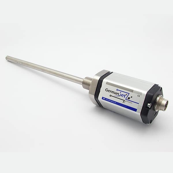
Step one: a three-point measurement to bring out the error shape
Park at 10%, 50% and 90% of measuring range, record the sensor reading and the measured mechanical position, and calculate the three error values. Three numbers are enough to characterise:
| Error shape | Three-point error feature | Most likely cause | Remedy direction |
|---|---|---|---|
| Constant error | The three errors are close in value and the same in sign | Zero set wrongly, or the magnet fitted in the wrong axial position | Reset zero / check the magnet installation dimension |
| Proportional error | Error grows approximately linearly with stroke | Wrong span factor (scaling upper and lower limits) | Re-measure the two end points; recompute the factor |
| Local error | Abnormal on one stretch only; the rest healthy | Magnet coaxiality/clearance, mechanical interference | Check mechanics and magnet installation in that stretch |
| Drifting error | The reading at the same point changes with time/temperature | Temperature drift, loose bracket, oil-debris build-up | Control temperature, anti-loosening, check oil cleanliness |
| Opposite direction | The reading changes in reverse with displacement | Counting direction / scaling upper and lower limits reversed | Reverse polarity or swap the scaling limits |
Note: the three points must be reached once in each direction. If the difference between forward and return readings at the same point clearly exceeds the order of repeatability (stated ±0.002 mm, which will degrade under site vibration), there is mechanical backlash or a loose magnet. Solve the repeatability problem first, then talk about error correction — any calibration is meaningless while repeatability is not acceptable.
Step two: check zero
Treatment of a constant error starts from zero. Check points:
- Whether zero is set on a reproducible mechanical datum: choosing an arbitrary mid position as zero will necessarily fail to match after a parts swap or overhaul;
- Whether the mechanics have been moved after calibration: changing seals, adjusting end-stops or reassembling the cylinder will all change mechanical zero;
- Whether fieldbus-type parameters were stored: a zero offset written online that has not had a store instruction executed reverts to the default on power-down, appearing as "it was right after adjustment and wrong the next day";
- Whether the magnet's axial position is the same as at installation: a loose magnet bracket backing off is equivalent to a zero offset; see Five Magnet Installation Pitfalls.
Step three: check the span factor
A proportional error means "the electrical quantity corresponding to each millimetre" was calculated wrongly. The most frequent cause is using drawing stroke in place of measured stroke: assembly tolerance, end-stop thickness and cushioning structure will all make actual stroke differ from the nominal. The remedy is to re-measure the raw values at the two end points and the actual mechanical distance, and recompute by the two-point method, rather than repeatedly trimming at zero. Worked example: if 0 mm reads 0 but 500 mm reads 525, the full span is 5 percent off; rescale the span, not the zero.
Another class is a mismatch between span and the sensor specification: scaling a 500 mm measuring-range sensor as 600 mm will systematically enlarge the reading over the full stroke. Check against the sensor nameplate and the factory report. For the mechanism of factory linearisation and dead-zone compensation see Factory Calibration and Linearisation.
Step four: check magnet position and the mechanical chain
Local errors are essentially all mechanical. On a cylinder-integrated type, focus on concentricity of the piston-rod deep hole and foreign matter in the hole (see Cylinder Bore Machining Requirements, Hydraulic Oil Cleanliness); on an external type, focus on bracket stiffness, slider float and parallelism (see External Installation). An easily overlooked phenomenon is: when bracket stiffness is insufficient, the reading at the same position differs between loaded and unloaded states, looking like "the sensor is inaccurate" when in fact the frame is deforming.
Step five: distinguish "error" from "not accurate enough"
Some error is set by the figures themselves and cannot be tuned out. Typical non-linearity <0.02%FS is a percentage of full scale: the same 0.02%FS corresponds to about ±0.02 mm on a 100 mm measuring range and about ±0.8 mm on a 4000 mm measuring range. If the user requires a long-range sensor to an absolute "±0.02 mm", that is not a fault but expected error. For the difference among the three accuracy figures see The Three Accuracy Terms of Magnetostrictive Sensors. Likewise, when the resolution step (1 / 2 / 5 / 10 / 20 / 50 / 100 μm) is chosen too coarse, the last digit of the reading changes in steps, which is also not a fault.
Step six: temperature and time
Drifting errors are mostly related to temperature. Waveguide acoustic velocity (about 2830 m/s) and mechanical structural length both change with temperature; a cold calibration and hot running will show zero slowly offsetting. Remedies include: recalibrate after system oil temperature is stable; on high-temperature duty choose a matching type (see Installing in High Temperatures and 19D split type); if necessary apply temperature compensation on the controller side. For the mechanism see Do Sensors Need Warm-Up? Self-Heating, Thermal Equilibrium and the Real Magnitude of Temperature Effects.
If it still cannot be located after troubleshooting, a second sensor can be used for cross-comparison — the most direct means of judging "which one is inaccurate"; for the method see Synchronizing Multiple Sensors. On the product side, high-accuracy closed-loop applications can refer to the configuration combination of Series 17 hydraulic cylinder integrated and the 191 analog series.
Practical tips for engineers
- The position magnet must not touch the sensor rod; the design clearance between them must be maintained.
- Fix the position magnet with screws, spacers and similar parts made of non-magnetic material, to avoid ferromagnetic parts disturbing the measurement.
- An M6 hexagon-socket setscrew is recommended for locking the position magnet — this screw is not supplied with the sensor and must be prepared separately.
Frequently Asked Questions
Q: A long-range sensor has a larger error than a short-range one. Is that a quality problem?
No. Non-linearity is a percentage of full scale; the same 0.02%FS is about ±0.02 mm on a 100 mm measuring range and about ±0.8 mm on a 4000 mm measuring range. The absolute error of a long measuring range is inherently larger — a mathematical necessity set by the measuring-range base. If a tighter absolute accuracy is needed, consider shortening the measuring range or a segmented calibration.
Q: Forward and return readings at the same point differ. Where is the problem?
This is a repeatability problem rather than an error problem, usually caused by mechanical backlash, a loose magnet, insufficient bracket stiffness or a binding slider. Any calibration is meaningless while repeatability is not acceptable; the mechanical problem must be solved first, then zero and span calibrated.
Q: How do I change a reading that is opposite to the actual direction of motion?
It is a configuration issue, not a fault. On an analog interface, swap the upper and lower limits of the controller scaling instruction, or choose a reverse-output type; on a fieldbus interface, write the counting-direction or polarity parameter, and after writing execute the store instruction, otherwise power-down will restore the default direction.
Q: The sensor is suspected of being inaccurate. How do I confirm that the reference itself is reliable?
The error of the reference gauge should be far smaller than the figure being judged. When a tape is used to measure a metre-scale measuring range, its own error may already be larger than the sensor non-linearity converted to that range, and the measured difference then has no judgement value. Where possible, use gauge blocks, laser interferometry or another known-good sensor for cross-comparison.
Related Products


Related Applications

Multi-Industry Application Cases for Magnetostrictive Displacement Sensors
View Details
Series 17 Hydraulic Cylinder Integrated Magnetostrictive Displacement Sensor Application Cases
View Details
Series 18 Profile Magnetostrictive Displacement Sensor Application Cases
View Details