
Magnetostrictive Displacement Sensor Oil Cleanliness and Filter Management
The in-cylinder rod of a magnetostrictive displacement sensor sits in oil long-term, so cleanliness governs rod life. The sensor itself has no contact and no wearing parts, and is in theory maintenance-free. But on a cylinder-integrated installation the rod is immersed in hydraulic oil, and the oil condition affects measurement by two paths: ferromagnetic debris is held by the magnet and builds up, changing the field distribution, and hard particles in the oil flow scour the rod surface and cause abrasion. Extending rod life is therefore, in essence, a hydraulic-system cleanliness-management problem, not a maintenance problem of the sensor itself. This article explains the mechanism of contaminants, the day-to-day actions that can be executed, and the replacement criteria. For the hydraulic-application background see Why Choose Magnetostrictive Sensing for Hydraulic Cylinder Position Control?; for the installation overview see Installing Magnetostrictive Displacement Sensors in Practice.
Ferromagnetic debris: the failure path most easily overlooked
Sources of ferromagnetic debris in a hydraulic system are wide: wear of pumps and valves, running-in of cylinder bore and piston rings, weld slag in pipework, machining swarf left behind. These particles circulate with the oil; once they enter the piston-rod centre-hole region they are held by the magnet's field and build up layer by layer.
The consequence is progressive: at first the build-up is small and the reading shows no clear change; as the build-up thickens, the magnet's equivalent field distribution is changed, the leading edge of the echo waveform deforms, appearing as local-stroke reading jitter or a small overall error; in severe cases the debris fills the clearance between magnet and rod and causes mechanical interference.
The identifying feature of this class of fault is "gradually worse" rather than "suddenly wrong": everything is normal when the machine is first put into service; after months of running the reading starts to be unstable; after cleaning it recovers in the short term and then recurs. If this pattern is found in troubleshooting, attention should move from the electrical side to the oil side, rather than repeatedly adjusting earthing and parameters (for electrical-side criteria see Signal Jump Troubleshooting Flow).
Hard-particle abrasion: the long-term effect on the rod surface
Hard particles in the oil (sand, scale, seal fragments) scour the rod outer wall with the high-speed oil flow; long-term action causes surface abrasion. Once the rod surface is broken, the protective layer fails, oil may enter the internal protective tube, and the waveguide eventually works abnormally. The process is usually measured in years, but it is clearly accelerated in systems whose cleanliness is chronically out of specification and whose oil-flow speed is high.
Contamination sources and control means
| Contamination type | Main sources | Effect on the sensor | Control means |
|---|---|---|---|
| Ferromagnetic debris | Pump and valve wear, weld slag, machining swarf | Held and built up at the magnet; reading degrades gradually | Return/circulation filtration, magnetic elements, thorough flushing before assembly |
| Hard particles | Ingress of external dust, scale | Scouring abrasion of the rod surface | Tank breathers; change elements on differential pressure |
| Water | Cooler leakage, condensation | Oil emulsifies; rusting is accelerated and new debris is produced | Control oil-temperature swing; test water content on a schedule |
| Air | Suction-line starvation, poor sealing | Cavitation accelerates component wear and indirectly produces debris | Check suction lines and their position |
| Oil ageing | Long-term high-temperature running | Sludge deposits; carrying capacity falls | Control temperature; change oil on test results |
The assembly stage is the most critical gate
One thorough flush before start-up beats half a year of later filtration, because deep-hole swarf is sealed in once the rod is fitted. A flush before the system is put into service is worth more than half a year of later filtration. This is especially true of a cylinder-integrated cylinder: deep-hole machining of the piston rod necessarily leaves swarf, which must be washed and blown out before the sensor is fitted — once the sensor is in, the swarf is sealed in the last place swarf should be. For deep-hole machining and cleanliness requirements see Cylinder Bore Machining Requirements.
A new system should also run a circulation flush: fit temporary flush elements, bypass the actuators, circulate the oil at high flow for a period, then fit the working elements and connect the loop that contains the sensor. This step is the one most often skipped on a rushed project, and the cost often shows three to six months after start-up.
Three executable actions in operation
- Change elements on differential pressure, not on the calendar: after the element is blocked the bypass valve opens and unfiltered oil enters the system directly; at that point it "looks as if it is still filtering" but has already failed. Follow a differential-pressure switch or gauge;
- Fit magnetic elements or magnetic bars: most effective against ferromagnetic debris, and they can also serve as a diagnostic — take them out on a schedule and look at the amount held; a clear increase means wear somewhere in the system has accelerated;
- Control oil temperature: high temperature accelerates oil oxidation and lowers viscosity, affecting both lubrication and the sensor's working environment. For installation notes on high-temperature duty see Installing in High Temperatures; for the effect of temperature on the measurement itself see Do Sensors Need Warm-Up? Self-Heating, Thermal Equilibrium and the Real Magnitude of Temperature Effects.
A judgement flow when oil is suspected
First confirm that the symptom matches the "progressive degradation + short-term recovery after cleaning" pattern, then confirm in this order: look at element differential pressure and whether the element appearance has a large amount of metallic-lustre particles → check how much the magnetic element has held → take an oil sample for a cleanliness test → where possible strip the cylinder and observe whether debris is adhering in the piston and magnet region. Draw the oil sample from the lowest reservoir point after the machine has stood, so the sample shows settled debris rather than clean surface oil. If it is confirmed as an oil problem, the treatment order is first treat the contamination source (find the wearing component), then flush and change oil, and only last clean or replace the sensor; if the order is reversed, a new sensor fitted will become dirty again. For systematic troubleshooting of reading errors see Tracking Down Reading Errors.
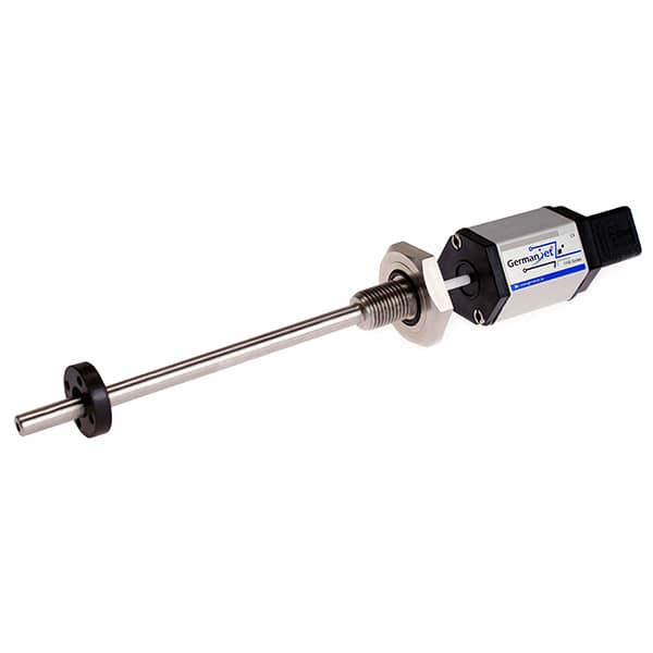
A product-side note: the rods of cylinder-integrated types such as Series 16 cylinder-integrated, Series 17 hydraulic cylinder integrated and 19H cylinder-integrated are immersed in oil long-term and are more sensitive to cleanliness. If system cleanliness is chronically hard to guarantee, or the oil itself is quite corrosive, consider switching to an external scheme (Series 18 external) so that the sensor is completely off the oil circuit.
Practical tips for engineers
- The position magnet must not touch the sensor rod; the design clearance between them must be maintained.
- Fix the position magnet with screws, spacers and similar parts made of non-magnetic material, to avoid ferromagnetic parts disturbing the measurement.
- An M6 hexagon-socket setscrew is recommended for locking the position magnet — this screw is not supplied with the sensor and must be prepared separately.
Frequently Asked Questions
Q: The reading gradually worsens and recovers in the short term after cleaning. What is the cause?
This is the typical signature of ferromagnetic debris building up at the magnet. The debris changes the field distribution around the magnet, deforming the echo waveform and degrading the reading; after cleaning it recovers in the short term but will build up again if the contamination source is not removed. Start from hydraulic-oil cleanliness: check element differential pressure, how much the magnetic element has held, and do an oil-sample test.
Q: Is changing filter elements on a fixed interval reliable?
No. After the element is blocked the bypass valve opens and unfiltered oil enters the system directly; on the surface it is still filtering, but it has already failed. Replacement should be based on a differential-pressure switch or gauge reading: change when differential pressure reaches the set value, rather than waiting for the calendar interval.
Q: What should be watched after a cylinder overhaul?
The repair process itself is a high-risk step for introducing contamination. After an overhaul or seal change, pipework and the bore must be flushed again, residual metal debris confirmed gone before the sensor is refitted, and the piston-rod deep hole checked for machining or strip-down residue; otherwise a newly fitted sensor will soon show the same progressive degradation.
Q: If system cleanliness is chronically hard to guarantee, is there an alternative?
Consider switching to an external installation so that the sensor is completely off the oil circuit. An external type measures through an external bracket and slider; the rod does not contact hydraulic oil, avoiding debris hold-up and particle scouring. The cost is that a suitable mounting datum must be found on the frame and bracket stiffness guaranteed.
Related Products




Related Applications

Multi-Industry Application Cases for Magnetostrictive Displacement Sensors
View Details
Series 16 Hydraulic Rod Magnetostrictive Displacement Sensor Application Cases
View Details
Series 17 Hydraulic Cylinder Integrated Magnetostrictive Displacement Sensor Application Cases
View Details