
Redundant Install of a Magnetostrictive Displacement Sensor: How to Compare Two Readings So It Actually Works
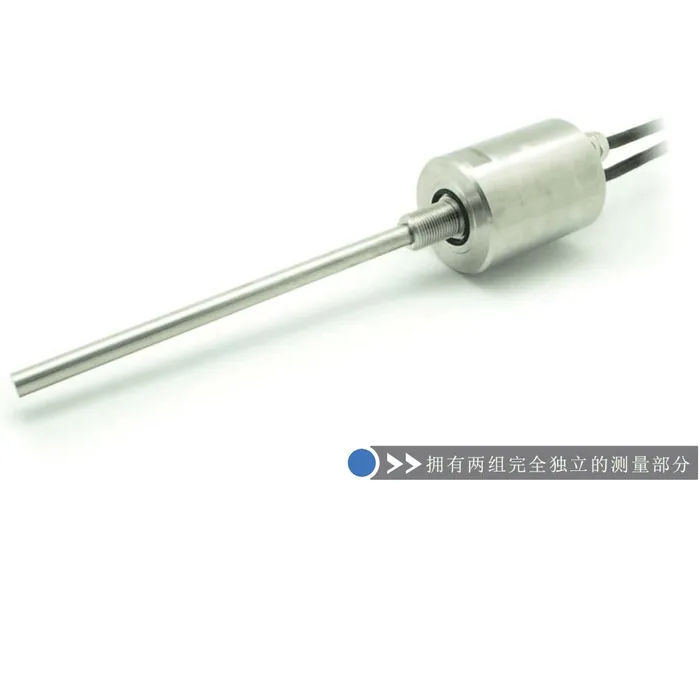
Redundancy on a magnetostrictive displacement sensor is a live comparison of two readings, not a spare kept in a cabinet. The purpose of redundant installation is not to add a spare; it is to let the system notice that it has measured wrongly. Fitting two channels without a comparison logic is spending twice the money for the reliability of one. This article covers the two forms of redundancy, how to set the comparison criteria, what to do when the deviation exceeds the limit, and the few things that must be done correctly at installation. For the design background, see what redundant output is; on the product side, see the 16R redundant cylinder-integrated.

Two forms of redundancy: dual channel vs. two sensors
| Dimension | Single-body dual channel (e.g. 16R) | Two independent sensors |
|---|---|---|
| Failures covered | Electronic output-channel failure | Body, position magnet, mounting and cable — the whole chain |
| Common-cause failure risk | Higher (shared rod and position magnet) | Lower (mechanically and electrically independent) |
| Installation complexity | Low — one installation | High — two mounting positions and two mechanical chains |
| Space occupied | Small | Large; cylinders often have no second mounting position |
| Typical use | Cylinder-integrated, space-limited, dual-output required | Safety-related, high diagnostic coverage required |
Selection principle: if the concern is failure of an output channel or a controller input channel, a single-body dual channel is enough; if the concern is mechanical and chain failures such as a magnet coming off, a damaged rod or a broken cable, two independent sensors are required, because a dual channel cannot cover failure of the shared parts. Cylinder-integrated space usually holds only one unit; in that case consider a heterogeneous combination of one cylinder-integrated sensor (for example the Series 16 cylinder-integrated) plus one external sensor (for example the Series 18 external), which also reduces common-cause failure probability.
Three critical points at the installation stage
- Both channels must measure the same physical quantity: if the two sensors sit at different points in the mechanical chain (one on the piston rod, one on the load end), the mechanical backlash and elastic deflection in between create an inherent offset and the comparison criterion cannot be set. If the structure cannot avoid this, that inherent difference must be recorded as a baseline at calibration;
- The two supplies and signal paths should be independent as far as possible: sharing one power supply, the same multi-core cable or the same I/O module lets the "redundancy" fail together when that supply or module fails;
- Calibrate the two channels independently: do not copy one channel's calibration parameters to the other. Complete a two-point calibration on each as in zero calibration step by step. Comparison assumes that each channel is accurate on its own.
How to set the comparison criterion
The comparison logic is usually written in the PLC: acquire both position values continuously, compute the absolute difference, and raise an alarm or trigger a safety action if the difference exceeds a threshold for longer than a set time. Three parameters need engineering judgement:
- Threshold: it should be greater than the sum of the two channels' reasonable inherent deviations. Sources include each channel's non-linearity (typically <0.02%FS, converted to millimetres for the actual range), repeatability (of the order of ±0.002 mm), the inherent mechanical-chain difference and temperature drift. Too small a threshold produces frequent false alarms; too large a threshold misses faults. Set the compare window wider than the two sensors’ own deviation, and raise the alarm only on a sustained out-of-band difference;
- Delay: during motion the two channels' response times and sampling instants are not identical, so the instantaneous difference is larger. A duration filter avoids false alarms in dynamics, but the delay must not be so long that it affects the safety response;
- Action: alarm only, switch to the trusted channel, or stop the machine — this depends on the equipment risk level and should match the safety design of the machine.
After the deviation exceeds the limit, how to tell which channel is wrong
When the two channels disagree, the system knows that "one is wrong" but not which. Locate them on site in this order:
- Look at the shape of the deviation: if one channel steps suddenly and the other is smooth, the stepped channel is the abnormal one; if both are smooth but slowly diverge, it is usually zero drift or a loosening bracket on one channel;
- Arbitrate with a third-party reference: stop the machine and measure the true position with a mechanical gauge, then compare with each reading — the most conclusive method;
- Verify the suspect channel alone with a test magnet: disconnect the suspect channel and walk a test magnet by hand over the full stroke to check whether the body is healthy; the method is in use a test magnet to verify in 5 minutes;
- Check each channel's independent links: magnet installation (see five magnet installation pitfalls), wiring and earthing, and controller-channel configuration.
The overall calibration method for multi-channel systems can be extended from synchronizing multiple sensors. If both channels are fieldbus types, first rule out "false deviation" caused by communication data loss; see fieldbus data loss.
What redundancy cannot solve
Be clear about the boundary: redundancy improves fault detectability, not measurement accuracy; the average of two channels is not more accurate than one. Redundancy also cannot cover common-cause failures — two sensors on the same loose bracket, sharing the same supply, or exposed to the same over-temperature will fail together with consistent readings, and the system will not notice. Redundant design must therefore also review common causes: mechanical mounting, supply, channels and environment should be independent wherever they can be.
Frequently Asked Questions
Q: Does fitting two sensors amount to redundancy?
No. Dual channels without a comparison logic are just buying an extra sensor. Continuous comparison must be implemented in the controller: compute the absolute difference, raise an alarm or trigger a safety action after the difference exceeds a threshold for longer than a set time, and define whether the action is a prompt, a switch-over or a stop.
Q: How do I choose between a single-body dual channel and two independent sensors?
It depends on the failure types to be covered. If the concern is failure of an output channel or a controller input channel, a single-body dual channel is enough. If the concern is mechanical and chain failures such as a magnet coming off, a damaged rod or a broken cable, two independent sensors are required, because a dual channel shares the rod and position magnet and cannot cover failure of those shared parts.
Q: How large should the comparison threshold be?
It should be greater than the sum of the two channels' reasonable inherent deviations, including each channel's non-linearity converted to millimetres for the actual range, the repeatability order of magnitude, the inherent mechanical-chain difference and temperature drift. Too small a threshold produces frequent false alarms; too large a threshold misses faults. Commission first with a looser value, observe the actual difference distribution, then tighten.
Q: When the two readings disagree, how do I tell which is correct?
Locate in four steps: first look at the shape of the deviation — a sudden step is the suspect channel; slow divergence is usually zero drift or a loosening bracket; then stop the machine and measure the true position with a mechanical gauge as a third-party arbitration; then verify the suspect body alone with a test magnet; finally check each channel's independent magnet installation, wiring and channel configuration.
Related Products



Related Applications

Multi-Industry Application Cases for Magnetostrictive Displacement Sensors
View Details
Series 16 Hydraulic Rod Magnetostrictive Displacement Sensor Application Cases
View Details
Series 17 Hydraulic Cylinder Integrated Magnetostrictive Displacement Sensor Application Cases
View Details