Why Choose Magnetostrictive Sensing for Hydraulic Cylinder Position Control? From Injection Molding to Metallurgical Presses
Hydraulic cylinders are one of the largest application areas for magnetostrictive displacement sensors. Why has cylinder position control become almost a "home ground" for magnetostriction? Because it hits exactly the operating conditions that hydraulic cylinders find hardest: long stroke, oil contamination, high temperature, and years of non-stop running. This article starts from those conditions.
| Cylinder pain point | What the sensor gives |
|---|---|
| Long stroke, 0.5–3 m | Non-contact absolute output across the full span |
| Oil contamination and sludge | No wearing slider inside the cylinder |
| Oil at 80–90 °C | Sealed in-cylinder rod, IP67–IP69K |
| Years of non-stop running | No brush to replace, maintenance-free life |
Why cylinder position is hard to measure
The working environment of a hydraulic cylinder is extremely unfriendly to sensors: the piston rod's reciprocating motion brings continuous friction and vibration; hydraulic oil temperature can reach eighty to ninety degrees; the site is full of metal swarf and oil sludge; strokes range from a few hundred millimetres to two or three metres. Traditional contacting displacement transducers (contact-based sensors, resistive scales) wear quickly here and have a short life, often drifting within a few months.
In-cylinder vs externally mounted: how the series map
By mounting method, magnetostrictive sensors fall into two broad groups. The split is simple: new designs with customisable bores choose the in-cylinder type; retrofits on standard cylinders choose the external type.
- In-cylinder (inside the cylinder): the sensor is fitted directly into the cylinder cavity, the rod is coaxial with the piston rod, and the position magnet is fixed to the piston. Representative products include the Series 17 hydraulic-cylinder integrated type and the Series 13 mobile hydraulic type (in-cylinder integration, IP68–IP69K, 25 g vibration / 100 g shock). The construction is compact and well protected, making it the first choice for injection molding machines and presses; Series 13 also suits construction-machinery cylinders.
- Externally mounted (outside the cylinder): the sensor is mounted on the cylinder body, with the magnet on the piston rod or on an added slider. Representative products include the Series 18 externally mounted type (floating type and rail type). Choose this when retrofitting older machines or when the cylinder cannot be opened.
Typical applications: from injection molding machines to metallurgical presses
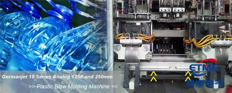
- Injection molding clamp / injection: an in-cylinder sensor feeds back screw and platen position in real time for closed-loop control of clamp force and shot size;
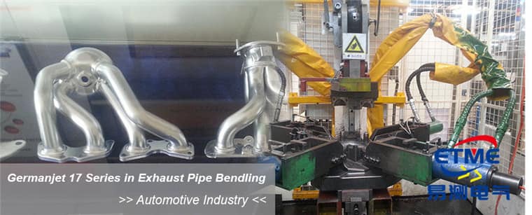
- Metallurgical / servo hydraulic presses: long stroke and high pressure, requiring profile or integrated types rated 300–600 bar;
- Water-conservancy gates / hoist machinery: outdoor, wet, long stroke, relying on high protection and maintenance-free operation on neglected sites.
The maintenance dividend of non-contact measurement
The position magnet and waveguide do not touch, which means there is no wearing mechanical friction part. Fitted once inside a cylinder, it will often run with the machine for years without attention. For a production line, avoiding one shutdown to change a sensor saves far more than the cost of the sensor itself.
For servo pressing and die-casting clamp in particular, response time and refresh rate must match the fast control cycle — check the refresh-rate guide before ordering.
Practical tips for engineers
- For in-cylinder mounting, piston-rod bore lower limit is ≥12.7 mm (Ø10 rod). Series 17 also has a Ø13 mm through-hole + M18×1.5 on the cylinder cap; Series 16 uses Ø18G7. Do not mix pressure ratings: Series 16/16R is 350 bar working / 530 bar peak, Series 17/17EX is 350/600 bar, Series 19 in-cylinder is 300/600 bar.
- The sensor rod inside the cylinder should be protected against wear.
- Series 19 in-cylinder types are rated 300 bar, 600 bar peak; use these figures for selection and pressure testing.
Frequently Asked Questions
Q: Why do most hydraulic cylinder position controls use magnetostrictive sensors rather than potentiometers or contacting transducers?
Because cylinder conditions hit exactly the weak points of contacting designs: the reciprocating piston rod brings continuous friction and vibration, hydraulic oil reaches eighty to ninety degrees, the site is full of metal swarf and oil sludge, strokes run from a few hundred millimetres to two or three metres, and the machine runs non-stop for years. Contacting types have wearing brushes that need periodic replacement and often drift within a few months here. A magnetostrictive sensor is non-contact and absolute, with no wearing friction part, so once fitted inside a cylinder it often runs with the machine for years.
Q: How do I choose between in-cylinder and externally mounted types?
The split is straightforward: new designs that can be supplied with a custom bore take the in-cylinder type; retrofits on standard cylinders, or where the cylinder cannot be opened, take the external type. In-cylinder products include the Series 17 hydraulic-cylinder integrated type and the Series 13 mobile hydraulic type (in-cylinder integration, IP68 to IP69K, 25 g vibration and 100 g shock), which are compact and well protected and are the first choice for injection molding machines and presses. Externally mounted types such as Series 18 (rail type and floating type) fit on the cylinder body with the magnet on the piston rod or an added slider.
Q: The inside of a cylinder is hot and dirty. Can the sensor survive it?
It survives through a sealed in-cylinder rod plus a high protection rating: in-cylinder integration reaches IP67 to IP69K, and with adequate oil cleanliness the rod can also be protected against wear, which is the precondition for long service in hydraulic oil. Bear in mind that the seals and connector are the weak link, since a failed connector seal defeats even the highest body rating.
Q: What bore and pressure figures must I check before mounting into a cylinder?
Check the bore first: the piston-rod bore lower limit is 12.7 mm with a Ø10 rod; Series 17 also has a Ø13 mm through-hole with M18x1.5 on the cap, while Series 16 uses Ø18G7. Then check pressure against system peak rather than working pressure alone: Series 16/16R is 350 bar working and 530 bar peak, Series 17/17EX is 350 and 600 bar, and Series 19 in-cylinder is 300 and 600 bar. Do not mix the pressure ratings between these series.
Q: Where does an injection molding machine use these sensors?
At clamp and injection: an in-cylinder sensor feeds back screw and platen position in real time for closed-loop control of clamp force and shot size. Related cases include long-stroke high-pressure metallurgical and servo hydraulic presses, where the in-cylinder integrated type must be selected against peak pressure, and outdoor wet long-stroke duties such as water-conservancy gates and hoist machinery, which rely on high protection and maintenance-free operation.
Related Products

Series 17 Hydraulic Cylinder Integrated
View Product
Series 13 Mobile Hydraulic
View Product
Series 16 Hydraulic Cylinder Built-in
View Product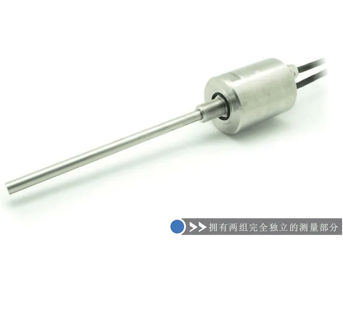
Series 16R Redundant Design Built-in
View ProductRelated Applications

Multi-Industry Application Cases for Magnetostrictive Displacement Sensors
View Details
Series 16 Hydraulic Rod Magnetostrictive Displacement Sensor Application Cases
View Details
Series 17 Hydraulic Cylinder Integrated Magnetostrictive Displacement Sensor Application Cases
View Details