
Magnetostrictive Displacement Sensor Series 16R: How Dual Output Catches Drift
Series 16R is the redundant-output version of Germanjet’s Series 16 cylinder-integrated magnetostrictive displacement sensor: a single sensor body provides two mutually independent position outputs for the control system to cross-compare and detect faults. It does not solve “measure more accurately”; it solves “when a single sensor fails, can the system detect it in time and enter a safe state”. It is suited to presses, lifting and mould clamping, where a distorted position signal can injure people or damage equipment. The mounting limits are the same as the Series 16 standard type: piston-rod bore minimum ≥12.7 mm; pressure rating 350 / 530 bar depending on model.
The core problem redundancy is meant to solve
Single-channel position sensing has a failure mode that is hard to notice: the sensor is still outputting, and the values still look plausible, but they have already left the true position. This “apparently normal wrong reading” is more dangerous than a complete open circuit — on an open circuit the controller can immediately declare a fault and stop; a slowly drifting wrong value is treated by the closed loop as truth.
The value of redundancy is a second independent source of information. The controller reads both positions; in normal operation the difference should lie within a very small tolerance band. Once the deviation exceeds the limit, at least one channel has failed, and degraded operation or a safety stop can be triggered. The basic concepts of redundancy and functional safety are in What redundant output is: dual-channel safety design.
How Series 16R implements dual channels
Series 16R realises two outputs in a single mechanical body. The direct engineering benefit is: only one mounting bore, one drilling operation and one set of seals. For a cylinder-integrated type this is especially important — drilling two deep holes in the same piston rod to fit two sensors is usually mechanically infeasible; neither strength nor machining allows it.
The level of redundancy must be stated clearly: Series 16R provides output-channel redundancy; the two signals can be acquired and diagnosed independently at the controller. That is different from device-level redundancy of “two fully independent sensors”, where the mechanical body, waveguide wire and mounting position are all independent and the probability of common-cause failure is lower, but the cost and space penalty are much higher. Which level to choose depends on what the safety analysis (for example the risk-assessment conclusion) requires for common-cause failure, not merely on whether the word “redundant” appears. Comparison and checking methods for a dual-sensor scheme are in Redundant installation: how to compare and check two sensors.
Single channel, Series 16R channel redundancy and dual-sensor device redundancy
| Comparison | Single channel (Series 16 standard) | Series 16R channel redundancy | Dual-sensor device redundancy |
|---|---|---|---|
| Number of outputs | 1 channel | 2 independent outputs | 2 sensors, 1 channel each |
| Detects drift faults | No; no comparison reference | Yes; two-channel cross-comparison | Yes, and covers mechanical common cause |
| Mechanical mounting | 1 bore | 1 bore | 2 independent mounting positions |
| Common-cause coverage | — | Partial (shared body and mounting) | Higher (independent bodies) |
| Cylinder modification | Low | Low; same as the standard type | High; usually infeasible for cylinder-integrated types |
| Controller requirement | 1 input | 2 inputs + comparison logic | 2 inputs + comparison logic |
| Typical application | General position control | Safety-related position on presses, lifting, mould clamping | High safety-integrity requirements |
Typical dual-output safety applications
Slide-position monitoring on a hydraulic press. Slide position is directly tied to the “closing-speed changeover point” and “safe height”. A low reading lets the machine keep descending at high speed in a zone where it should already have slowed. Two-channel comparison can cut the down-stroke immediately when the deviation exceeds the limit.
Lifting and lift platforms. Position drift can cause overtravel or landing at the wrong level. Redundant channels can form an independent second layer of protection with limit switches — note that a redundant sensor does not replace hard limits; they are different layers of protection.
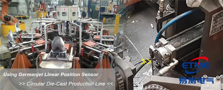
Mould clamping on injection molding and die-casting machines. Clamp position involves mould and personnel safety; comparison logic is often used with a safety PLC. Background on hydraulic position control is in Why choose magnetostrictive sensing for hydraulic cylinder position control.
Designing comparison logic on the controller
Hardware redundancy is only meaningful with correct software comparison. Three things must be defined in engineering:
- Tolerance-band width: the maximum allowed deviation between the two readings. The value must cover the repeatability of both channels (of the order of ±0.002 mm) and the difference in non-linearity. Too narrow causes false trips; too wide loses detection capability. Parameter meanings are in The three accuracy figures.
- Duration criterion: the deviation must persist for several control cycles before a fault is declared, to avoid a single sample of noise causing a false stop.
- Fault-response action: immediate stop, switch to a safe speed, or alarm-only degraded running — this must be decided by the risk assessment.
In addition, the comparison logic itself should be self-tested periodically — a safety function that never trips for a long time may already have failed without anyone knowing. The evolution of functional-safety standards is covered in How to read functional safety SIL.
Selection and installation notes
The mechanical installation requirements of Series 16R are the same as the Series 16 standard type: piston-rod minimum bore ≥12.7 mm, bore depth covering the full stroke plus allowance, with deep-hole straightness the key point. Machining requirements are in Bore machining requirements for cylinder-integrated sensors. Choose the 350 / 530 bar type on system peak pressure, not on the relief-valve set point; see Series 16 explained.
On the wiring side, leave an independent channel for each output. Do not merge them onto the same isolation domain of the same module to save wire — a shared isolated supply or a shared A/D introduces a new common-cause failure point and weakens the redundancy. If the machine uses a fieldbus architecture, confirm that the master supports independent mapping of two position objects. See the Series 16R product page and Comparing the whole cylinder-integrated range. For three independent measurements in one tube rather than dual channel, see Series 16T triple redundancy.
Practical tips for engineers
- For in-cylinder mounting, piston-rod bore lower limit is ≥12.7 mm (Ø10 rod). Series 17 also has a Ø13 mm through-hole + M18×1.5 on the cylinder cap; Series 16 uses Ø18G7. Do not mix pressure ratings: Series 16/16R is 350 bar working / 530 bar peak, Series 17/17EX is 350/600 bar, Series 19 in-cylinder is 300/600 bar.
- The sensing rod inside the cylinder should be protected against wear.
- Series 19 cylinder-integrated types are rated 300 bar, 600 bar peak; use these figures for selection and pressure testing.
Frequently Asked Questions
Q: Why does a displacement sensor need redundant output?
A single channel has a hard-to-notice failure: the sensor is still outputting and the values look plausible, but they have already left the true position. This drift-type error is treated by the closed loop as truth. With a second independent output, the controller can cross-compare; when the deviation exceeds the limit it declares a failure and enters a safe state.
Q: What is the difference between Series 16R channel redundancy and fitting two sensors?
Series 16R provides output-channel redundancy: the two signals are acquired and diagnosed independently, but they share the mechanical body and mounting position. Fitting two sensors is device-level redundancy: body and mounting are both independent, so the probability of common-cause failure is lower, but cost and space are higher. Drilling two deep holes in the same piston rod is usually infeasible, so Series 16R is the practical in-cylinder redundant solution.
Q: Can the two redundant readings be averaged?
Not recommended. Averaging masks the deviation between the two channels and loses the point of comparison and fault detection. Redundancy is a means of detecting faults, not of improving accuracy. The two channels should be acquired separately and judged on deviation.
Q: How should the Series 16R comparison tolerance band be set?
The band must cover the repeatability of both channels (of the order of ±0.002 mm) and the difference in non-linearity. Too narrow causes false trips; too wide loses detection. Start at several times the sum of the repeatabilities, then back-calculate the final value from the measured deviation distribution after installation, and use a duration criterion so that a single sample of noise does not trip a stop.
Related Products

Series 17 Hydraulic Cylinder Integrated
View Product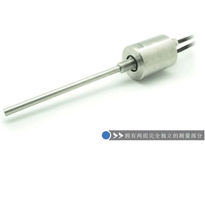
Series 16R Redundant Design Built-in
View Product
Series 19 H-Type Built-in Cylinder
View Product
Series 16 Hydraulic Cylinder Built-in
View ProductRelated Applications

Multi-Industry Application Cases for Magnetostrictive Displacement Sensors
View Details
Series 16 Hydraulic Rod Magnetostrictive Displacement Sensor Application Cases
View Details
Series 17 Hydraulic Cylinder Integrated Magnetostrictive Displacement Sensor Application Cases
View Details