
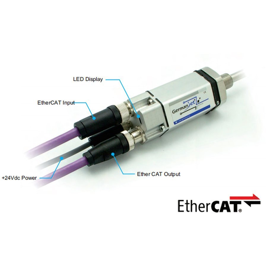
Series 19 EtherCAT bus magnetostrictive displacement sensor
EtherCAT slave, distributed clock sync, ESI file
The Series 19 EtherCAT version connects to industrial Ethernet as an EtherCAT slave and supports distributed clock (DC) synchronization for extremely high real-time performance. An ESI device description file is provided for seamless integration with Beckhoff TwinCAT and other systems. IP67 protection.
Product Overview
Series 19 with EtherCAT interface is an open fieldbus system fully conforming to the EtherCAT fieldbus standard. Data is exchanged over error-free Ethernet (IEEE 802.3) transmission technology at up to 100 Mbit/s. It has become the IEC/PAS 62407 standard and forms part of ISO 15745-4.
The sensor is networked via D56 series-connected connectors and offers extensive system diagnostics. Installation is quick and convenient: using the system management software (TwinCAT from Beckhoff), the user can retrieve all sensor parameters from the XML file.
Operates as an EtherCAT slave with distributed clock (DC) synchronization, achieving sub-microsecond synchronization in multi-axis systems. Its real-time performance far exceeds that of conventional fieldbuses, making it ideal for high-dynamic servo and motion control. IP67 protection for harsh industrial sites.
Operating Principle
The Series 19 EtherCAT version implements the EtherCAT slave protocol on top of the standard magnetostrictive measurement principle. Position data is read and processed in real time as the Ethernet frame flies past, and together with Distributed Clock it achieves sub-microsecond synchronisation accuracy for highly dynamic motion control.
Typical Applications
Technical Specifications
| Output | EtherCAT Ethernet control technology |
|---|---|
| Measured Data | Linear displacement |
| Data Format | EtherCAT 100 Base-TX Fast Ethernet |
| Transmission Speed | 100 Mbit/s |
| Bus Protocol | EtherCAT (CoE) |
| Synchronization | Distributed clocks DC (sub-microsecond) |
| Repeatability | < 0.001% FS (min. ±2.5 µm) |
| Resolution | Displacement: adjustable 1~1000 µm / Velocity: 1 µm/s (limited by speed and measuring length) |
| Non-Linearity | < 0.01% FS (min. ±50 µm) |
| Update Time | 0.5ms(≤500mm) / 1.0ms(≤2000mm) / 2.0ms(≤4500mm) / 3.1ms(≤7600mm) |
| Power Supply | +24V DC (20.4 ~ 28.8 Vdc) |
| Input Protection | Polarity protection to -30 Vdc, overvoltage protection to 36 Vdc |
| Power Consumption | 80 mA (depending on measuring range) |
| Dielectric Strength | 500 Vdc (DC ground to housing ground) |
| Connector | Two 4-pin M12 connectors (D56 socket: data side M12 female socket 1 = Tx+ / 2 = Rx+ / 3 = Tx− / 4 = Rx−; power male socket 1 = +24 V / 2 = not connected / 3 = 0 Vdc / 4 = not connected) |
| Protection Class | IP67 (with connector) |
| Operating Temperature | -40 °C to +75 °C (90% humidity, non-condensing) |
| Vibration | 15g / 10~2000Hz / IEC 68-2-6 |
| Shock | 100 g single shock / IEC 68-2-27 |
| EMC | EN 61000-6-3 / 6-2 / 4-2/3/4/6/8 |
| Measuring Range | By mounting version: 19H 75~475 / 19P 125~4050 / 19D 75~475 / 19F from 2500 mm (≤ 7600) |
Models and Output Signals
Dimensions and Wiring Diagrams
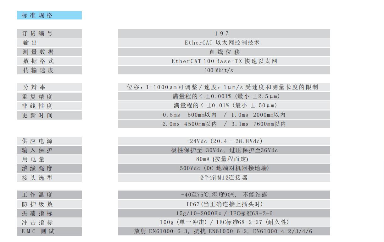
197 EtherCAT standard specification table
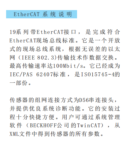
EtherCAT system description
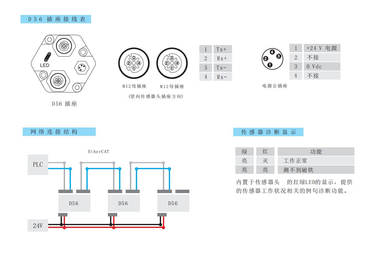
D56 socket wiring table / network connection structure / LED diagnostic indication
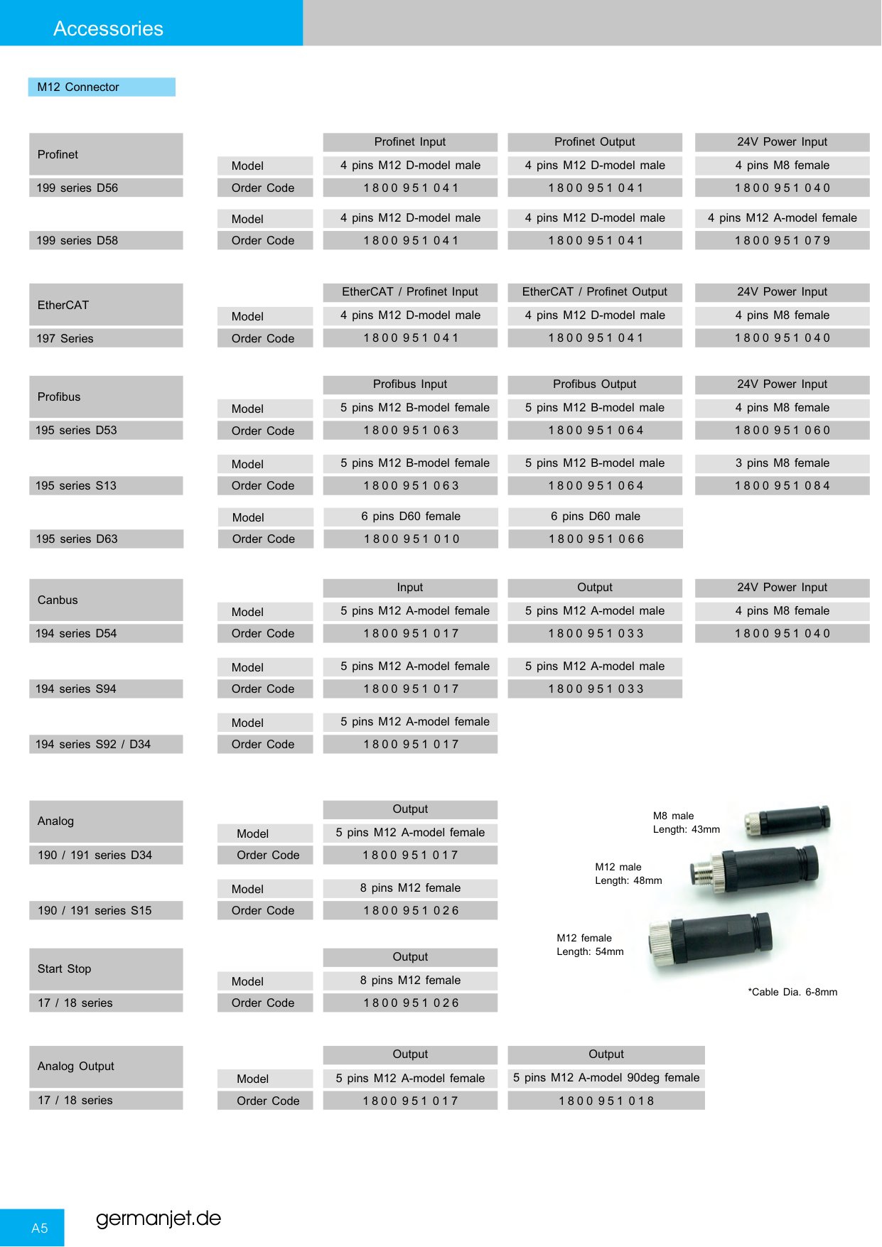
Series 19 connectors and socket types overview
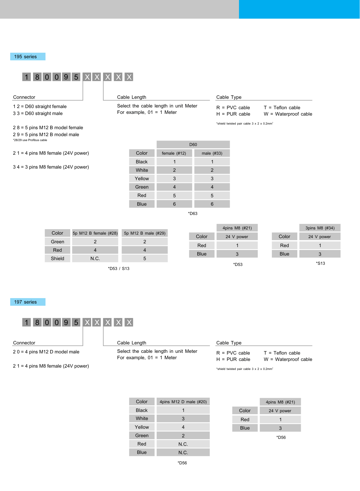
197 EtherCAT bus wiring diagram
Installation Precautions
- On an EtherCAT network the slave address / topology must be configured correctly. D56 socket data side pins: 1 = Tx+ / 2 = Rx+ / 3 = Tx− / 4 = Rx−; power side: 1 = +24 V / 3 = 0 Vdc.
- Use industrial-grade shielded Ethernet cable and avoid long parallel runs with high-power lines.
- Import the ESI (XML) file into TwinCAT or another master, then verify DC synchronization and process data mapping.
- Built-in LED diagnostics: green steady + red off = normal operation; both on = no magnet detected / magnet ring not in position.
- Regardless of the output interface, the physical installation of Series 19 must comply with the following: the ring magnet must not touch the rod; when built into a cylinder, piston-rod bore ≥12.7 mm (Ø10 rod); Series 19 in-cylinder is 300 bar working / 600 bar peak — never exceed that series peak; the rod must be protected against wear.
- EtherCAT mating connectors : 1800 951 041 (M12 D-coded class) and 1800 951 040 (M8 class). Confirm pin count on the accessory page.
Pricing Notes
The price of the Series 19 EtherCAT bus version depends on the communication protocol, measuring range and mounting method. Please provide the master brand and bus requirements to obtain a quotation.



Technical Articles
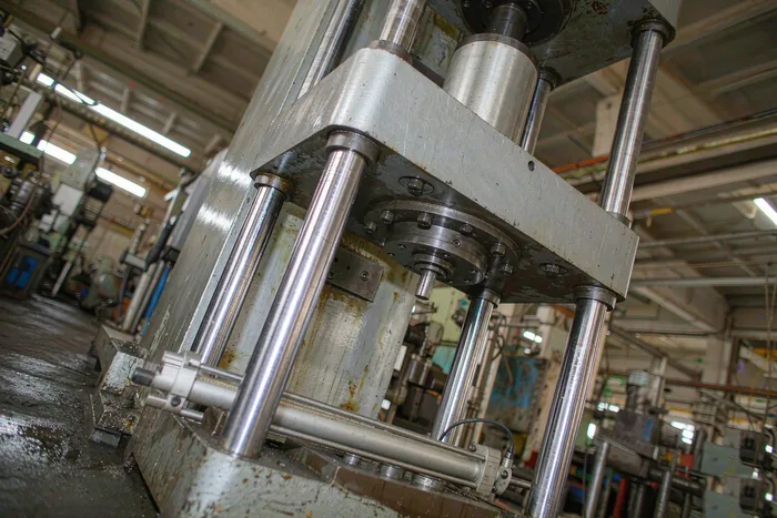
Mechanical, Divider Valve or Servo Closed Loop: Choosing Between Three Ways to Sync Cylinders
Read More
Magnetostrictive Displacement Sensor on Industrial Ethernet: PROFINET vs EtherCAT
Read More
Four-Layer Cloud Path for a Magnetostrictive Displacement Sensor: Field, Control, Edge and Platform
Read More
Magnetostrictive Displacement Sensors: Core Components and Selection Evaluation Dimensions
Read More
How to Network Displacement Sensors Under Industry 4.0
Read More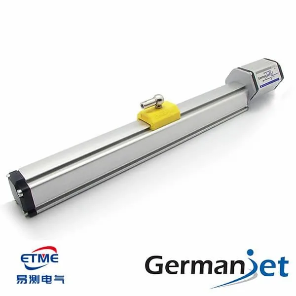
On-Site EMC Fixes for a Magnetostrictive Displacement Sensor: Breaking Source, Path and Victim
Read MoreRelated Applications

Series 19D Split-Type Process Displacement Sensor Application Cases
View Details
Series 19H Cylinder-Integrated Process Displacement Sensor Application Cases
View Details