
Mechanical, Divider Valve or Servo Closed Loop: Choosing Between Three Ways to Sync Cylinders
A specification for a machine that needs several cylinders moving together usually offers three options: add a synchronising shaft or rack and pinion, use a divider or synchronising valve, or fit every cylinder with its own valve and magnetostrictive displacement sensor and close a loop. The prices differ by a multiple, and the maintenance requirements differ just as much.
It is easy to be led by price. Try a different thread instead: the three methods differ in what force actually enforces the synchronisation. Once that is clear, the boundaries fall out.
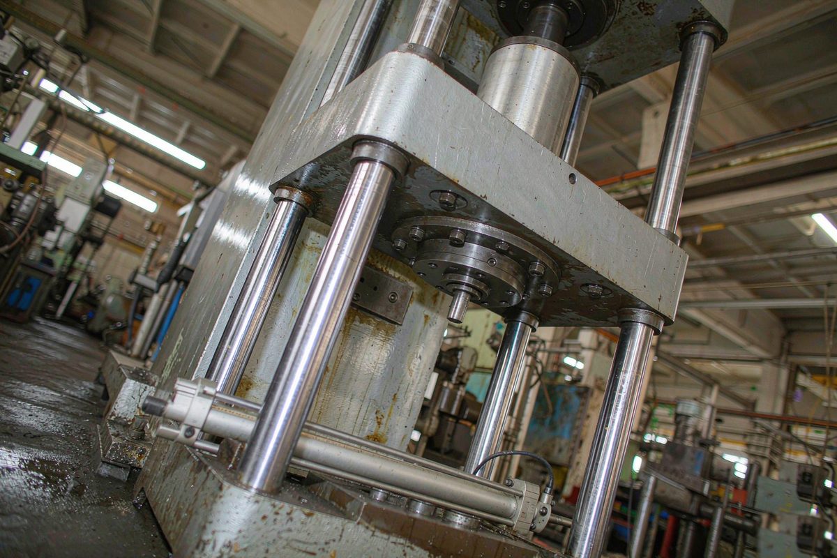
Mechanical sync: structure enforces it, not control
Rack and pinion with a torque shaft, a rigid linkage, a shared synchronising shaft — what these share is that the two cylinders are hard-coupled. Neither can go where the other is not. Sync is not controlled, it is connected.
The advantages are concrete: no dependence on electrics or oil condition, sync maintained through power loss, and a failure mode anybody can read — either the gearing wears into backlash or a coupling works loose. Maintenance is mechanical work, handled by a millwright.
The costs sit in three other places. It takes space, and a long span needs a stiff shaft, which means a thick and heavy one. Inertia is high, which hurts fast cycling. Wear produces backlash, and that error grows rather than returning to zero. The wider the span and the longer the stroke, the harder the structure becomes.
Divider valve sync: splitting flow
Divider valves, synchronising valves and gear flow dividers all belong here: one supply is split in a fixed ratio and each path drives its own cylinder. There is no position value in the circuit; the basis for splitting is flow.
The advantages are simplicity, low cost and no electrical dependency. The drawback is equally clear: split tolerance, asymmetric load, oil compressibility, internal leakage and oil temperature drift stay uncorrected, so the position difference accumulates along the stroke. When a datasheet quotes a split accuracy percentage, check what flow, what pressure differential and what oil temperature it was measured at.
Where it fits shares one feature: the error never gets a chance to accumulate into the product. Short strokes, intermittent motions, and a mechanical stop taking over at the end of travel — those conditions make a divider valve economical.
Servo closed loop: position feedback maintains it
Each cylinder gets a proportional or servo valve and a magnetostrictive displacement sensor, plus a controller that compares actual positions and corrects each cycle. The synchronisation is maintained by the control loop rather than by the valve characteristic.
The accuracy band is genuinely different, but the costs need stating: valve and magnetostrictive displacement sensor hardware, sensitivity to oil cleanliness, commissioning effort, and the need for somebody on site who can read the controller parameters. One more cost is easy to miss — sync accuracy becomes tied to the position feedback itself. A reading problem becomes a sync problem, so mounting and calibration have to be done properly. Mounting is covered in external and in-cylinder mounting, calibration in zeroing with a mechanical datum.
Side by side
| Item | Mechanical sync | Divider valve sync | Servo closed loop |
|---|---|---|---|
| What maintains sync | Rigid structural coupling | Flow split in a fixed ratio | Position feedback correction |
| Does the error accumulate | No, but backlash grows | Yes, along the stroke | No, corrected continuously |
| Response to load change | Structure absorbs it, may distort or bind | Poor, load difference becomes position difference | Good, loop compensates |
| Long spans and strokes | Structure becomes impractical | Largely unaffected | Largely unaffected |
| Electrical dependency | None | None | Strong |
| Maintenance skill | Mechanical only | Mechanical, mostly hydraulic | Hydraulic plus controls |
| Diagnosability | Inspect backlash and wear | Effectively invisible until it fails | Deviation and trend readable online |
| Cost band | Depends on structure, rises fast with span | Low | High |
Three steps to choose
- Step one: convert the sync requirement into a percentage of stroke. Around one percent allows a conversation about divider valves. A few parts in a thousand, or a fixed figure in millimetres, means closed loop. The conversion is covered in building an error budget.
- Step two: ask whether the error gets a chance to accumulate. A motion of a few tens of millimetres that stops at a hard stop gives the error no time. A motion that runs for minutes, or that must hold sync at any intermediate position, accumulates every time.
- Step three: check whether mechanical guidance is already doing part of the work. Tie rods on a four-column press, guideways on a gantry, a scissor linkage — each of them carries some of the synchronising constraint, which allows a lighter electrical solution.
Those three steps settle most cases. The genuinely awkward ones are the middle ground where none of the three fits cleanly, and that is where combinations come in.
Where the methods are combined
The three approaches can share one machine. Two combinations are common.
Mechanical guidance, hydraulic drive, position monitoring. The guideways or tie rods constrain the sync, the hydraulics provide the force, and the magnetostrictive displacement sensor readings are used to detect abnormality. In this arrangement it only monitors and takes no part in the loop, so cost comes down — accept that it can only report a problem, not correct it.
Master-slave. One cylinder follows the command, the other follows the first cylinder's actual position. The two cannot drift apart independently, at the price of the master's following error being passed straight to the slave, capping overall accuracy at the master. A fully peer-to-peer arrangement costs more but does not pass error in one direction only.
Where redundant monitoring is specified there is one further consideration: two magnetostrictive displacement sensors only earn their cost if the readings are genuinely compared. Installation without comparison achieves nothing — the method is in double sensors that are never compared.
Field notes for engineers
- When asking a supplier for a sync accuracy figure, ask three questions with it: at what flow, at what pressure differential, and at what oil temperature. A single number without those qualifiers is usually the most favourable condition available.
- Where a servo closed loop is already installed and underperforming, do not suspect the control algorithm first. Check two things: whether every axis was zeroed against the same mechanical datum, and whether the sampling instants really are simultaneous. Get either wrong and the loop will hold a wrong state very steadily.
- Maintenance capability is the most commonly overlooked selection criterion. Without anyone who can read an electrical drawing, every fault on a closed-loop system waits for outside support, and the downtime cost overtakes the hardware price difference.
Frequently Asked Questions
Q: Mechanical sync uses no electrics. Is it the most reliable option?
Separate two meanings of reliable. It does not depend on power or oil condition, and its failure modes are visible — both real advantages. But backlash in gearing and couplings grows with wear, and that error does not return to zero on its own, so it eventually means a shutdown for adjustment or replacement. The wider the span and the longer the stroke, the harder structural rigidity becomes, and the advantage shrinks.
Q: Two cylinders on our machine need only loose sync and two need tight sync. Can we mix methods?
Yes, and this is common in practice. Run the tight pair closed loop, leave the others on divider valves or mechanical constraint — provided the motion relationships are clear. If they all belong to one kinematic chain, a closed-loop axis gets dragged by an open-loop one and the sync relationship breaks. Draw the motion chain first, then group.
Q: Master-slave or peer-to-peer sync: how do you decide on site?
Look at whether one-directional error transfer is acceptable. In master-slave the slave follows the master's actual position, so the master's own error passes through one to one and overall accuracy is capped by the master. The control logic is simpler and the two axes cannot fight each other. In peer-to-peer both axes take part in the computation, giving higher accuracy, but simultaneous correction can cause them to pull against each other, so tuning is finer.
Q: With a servo closed loop installed, should mechanical guidance stay?
Keep it. Mechanical guidance carries part of the constraint, which reduces the correction burden on the loop and keeps lateral force off the magnetostrictive displacement sensor. Removing the guidance and relying purely on the loop for geometric relationships loads every stiffness requirement onto the control system, demanding more from both valve response and reading consistency. That is a poor trade.
Related Products



Related Applications

Multi-Industry Application Cases for Magnetostrictive Displacement Sensors
View Details
Series 12 General-Purpose Magnetostrictive Displacement Sensor Application Cases
View Details
Series 16 Hydraulic Rod Magnetostrictive Displacement Sensor Application Cases
View Details