
Why One Divider Valve Cannot Keep Two Cylinders Together: Four Errors Open Loop Never Corrects
Two cylinders push one beam. The specification says stay synchronised, position difference within 0.5 mm across the full stroke. Both commands are identical, both valves are the same model, and the beam still runs crooked. That is the usual opening of a multi-cylinder sync problem.
The first reaction on site is to adjust the divider valve, or add a synchronising valve in series. It helps, briefly. Then the beam drifts again, and drifts harder the moment the load changes. This article separates where those errors actually come from: an open loop carries four of them all the time, and none of them is a tuning problem.
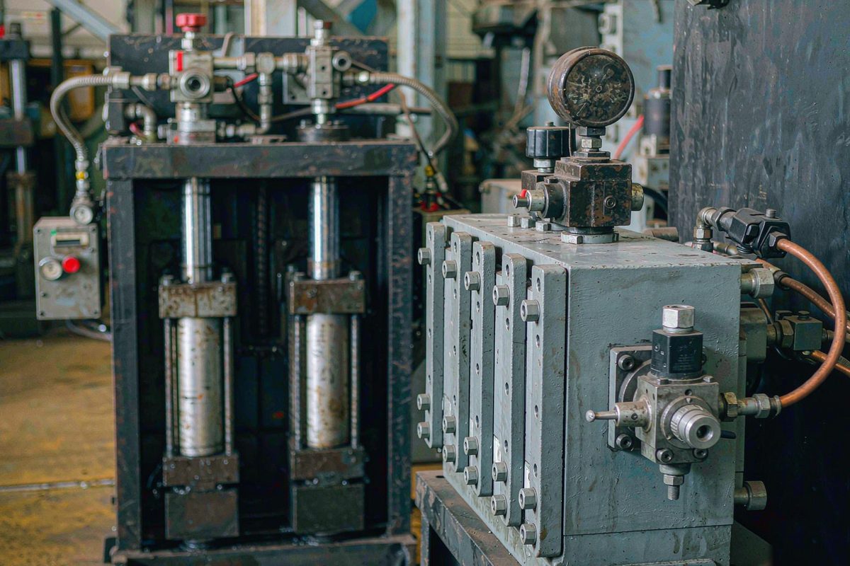
Position sync and velocity sync are not the same thing
Most arguments on site stall on this word pair. Velocity sync means the two cylinders travel at matching speed. Position sync means the actual position difference stays inside a tolerance at every moment.
Good velocity sync does not deliver position sync. Any non-zero velocity error accumulates, and by the time the stroke ends the difference can be tens of millimetres. A position-synced system, conversely, tolerates brief velocity differences because the position difference is pulled back continuously.
That decides the selection direction: a scheme that only distributes flow is doing velocity sync. Guaranteeing position requires a position value in the circuit.
The four errors in an open loop
Divider valves, synchronising valves and gear flow dividers share one trait: they approach sync by splitting flow, with no position value involved. These four errors are therefore always present, and none of them belongs to the category of "needs adjusting".
The flow split itself has a tolerance
Split accuracy is a published figure, typically a few percent, measured at rated flow, rated pressure differential and stable oil temperature. Move away from those conditions and the error grows. At a few percent, an 800 mm stroke can end up tens of millimetres out on a single traverse — before the other three errors are counted.
Asymmetric load shifts the flow
A divider valve splits flow, not position. When the two cylinders see different loads — off-centre tooling, an offset beam centre of gravity, different friction on the two sides — the higher-pressure path carries less flow and the lower-pressure path carries more. The direction is fixed: the heavily loaded cylinder always falls behind.
Oil compresses, so pressure difference becomes position difference
Hydraulic oil is not rigid. Oil in a closed chamber changes volume under pressure, and the effect grows with bore size and oil column length. Different pressures mean different compression, which means different positions. This term moves with pressure: change the tooling or the station and it changes with it.
Internal leakage and oil temperature make the error drift
Cylinder leakage, spool leakage and viscosity changes with oil temperature all shift the flow split slowly. The signature is: aligned at start-up, drifting after an hour or two, worse in summer than in winter. What makes this one awkward is that it changes — the parameters that worked today are wrong tomorrow.
Where open-loop compensation runs out
One reasonable next thought is to add a proportional valve and compensate the measured deviation. That is already heading towards closed loop, but as long as no genuine position value exists anywhere in the circuit the compensation amount can only be estimated — from pressure, from time, from spool position. Estimates follow inputs that move, so the compensation does not land accurately.
The more basic problem is that an open loop does not know how far out it is. A 0.3 mm difference and a 3 mm difference provoke the same response, because the deviation is never measured at all. Without a deviation value there is no feedback, and without feedback there is no correction.
What changes once position enters the loop
Wire the actual position of both cylinders back to the controller and the circuit stops distributing flow and starts controlling position. Three things change:
- The error becomes measurable. The controller reads both positions each cycle and computes the difference directly instead of estimating it.
- Accumulation is cut off. The deviation is corrected as soon as it exceeds the limit, not discovered at the end of the stroke.
- Drift is tracked. Offsets caused by oil temperature, leakage and load all appear in the position readings, and the loop takes them out.
The meaning of sync accuracy changes as well: it no longer depends on the valve's split accuracy but on magnetostrictive displacement sensor resolution, the consistency of sampling instants, and how the control cycle matches the hydraulic response. How to read its figures is covered in resolution, repeatability and non-linearity, aligning sampling instants in multi-axis synchronisation, and setting the sync target itself in building an error budget.
When a divider valve is genuinely enough
To be fair to the divider valve: it is cheap, simple, and needs no electrics. It is sufficient when all of these hold at once:
- The two load paths are broadly symmetric and stay that way.
- The position tolerance is loose — around one percent of stroke is acceptable.
- Motions are short and intermittent, so the error has no time to accumulate.
- Mechanical guidance is already constraining sync passively, such as the tie rods of a four-column press or the guideways of a gantry.
Step outside those conditions — off-centre tooling, a 0.5 mm requirement, or a motion that runs for minutes — and the scheme has to be reconsidered. Whether to go closed loop can be judged from the limits in when not to fit a displacement sensor, and the timing budget for multiple axes is in how many axes one bus can carry.
Points to settle when deploying closed-loop sync
| Item | What to do | Common mistake |
|---|---|---|
| Magnetostrictive displacement sensor placement | One per cylinder, each measuring its own position | One at one end of the beam, the other end inferred |
| Datum | All axes zeroed against one mechanical datum | Each cylinder zeroed at its own retracted position — readings all zero, beam still crooked |
| Sampling instant | All axes sampled at the same moment | Sequential reads produce speed-dependent phantom deviations |
| Control cycle | Faster than the hydraulic response | Control cycle slower than the valve, so the loop chases its own tail |
| Range margin | Cover the full stroke with margin | Range pressed against the stroke end, running into the dead zone |
Mounting a magnetostrictive displacement sensor differs between in-cylinder and external types; the in-cylinder case is covered in the hydraulic cylinder sensor guide, and bracket rigidity and parallelism for external types in how to build a stable mounting bracket. For long cable runs, see shield earthed at one end or both.
Field notes for engineers
- A quick way to separate velocity sync from position sync: run the cylinders a short distance, stop, and look at the difference. If it slowly returns towards zero after stopping, you are looking at velocity sync. If it stays exactly where it stopped, the offset is already fixed in the mechanics or the calibration.
- Archive the sync baseline — the curve of axis-to-axis difference against stroke position. Comparing the shape later tells you which axis degraded first, the same approach used in spotting early degradation from the position curve.
- Do not accept a test at no load only. Run the full stroke at no load, half load and full load. The asymmetric-load error is invisible when there is nothing on the machine.
Frequently Asked Questions
Q: If the two loads are perfectly symmetric, is position feedback unnecessary?
Symmetric load removes one of the four error sources only. Flow split tolerance, oil compressibility, internal leakage and oil temperature drift are still there, just slower to show. The real test is not whether the loads match but how much position difference is allowed, and whether mechanical guidance can constrain it passively. On a four-column press the tie rods may genuinely be enough.
Q: We already run a divider valve. Can we just add one magnetostrictive displacement sensor for monitoring?
Yes, but be clear that it can only reveal the problem, not correct it. One magnetostrictive displacement sensor at one end measures that end; the other end is still inferred. When monitoring shows an out-of-tolerance difference there is no means in the circuit to act on it. That arrangement is useful for deciding whether to move to closed loop. It is not a closed loop.
Q: Once position is in the loop, what sync accuracy is realistically achievable?
It depends on three things: magnetostrictive displacement sensor resolution and repeatability, how consistently the axes are sampled, and how the control cycle matches the hydraulic response. Its non-linearity is typically in the range of a few parts in ten thousand of full scale, and that stacks with mechanical chain tolerance and thermal drift. A sync requirement tighter than the sum of those cannot be met by any loop, and will simply alarm continuously.
Q: Sync gets worse as the oil warms up. Can control compensate for that?
Partly, but look at the hydraulic side first. Rising oil temperature changes viscosity, internal leakage and bulk modulus together, and the loop can follow the resulting position offset only while it stays inside the actuator's authority. If the valve's split characteristic has shifted badly, fixing cooling and oil condition is more effective than piling compensation into the controller.
Related Products
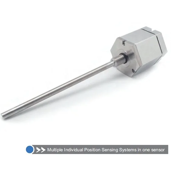
Series 16T Triple Redundant
View Product
Series 17 Hydraulic Cylinder Integrated
View Product
Series 19 H-Type Built-in Cylinder
View Product
Series 16 Hydraulic Cylinder Built-in
View ProductRelated Applications

Multi-Industry Application Cases for Magnetostrictive Displacement Sensors
View Details
Series 16 Hydraulic Rod Magnetostrictive Displacement Sensor Application Cases
View Details
Series 17 Hydraulic Cylinder Integrated Magnetostrictive Displacement Sensor Application Cases
View Details