Hydraulic Cylinder Displacement Sensor: Principle, Wiring, Mounting, Parameters
A hydraulic cylinder displacement sensor is usually a magnetostrictive sensor built into the cylinder: the rod enters through the head, the magnet ring sits on the piston, and the position is measured without contact. This article covers the in-cylinder principle, wiring, mounting rules, parameters and how to pick a brand.
Principle: why in-cylinder magnetostrictive
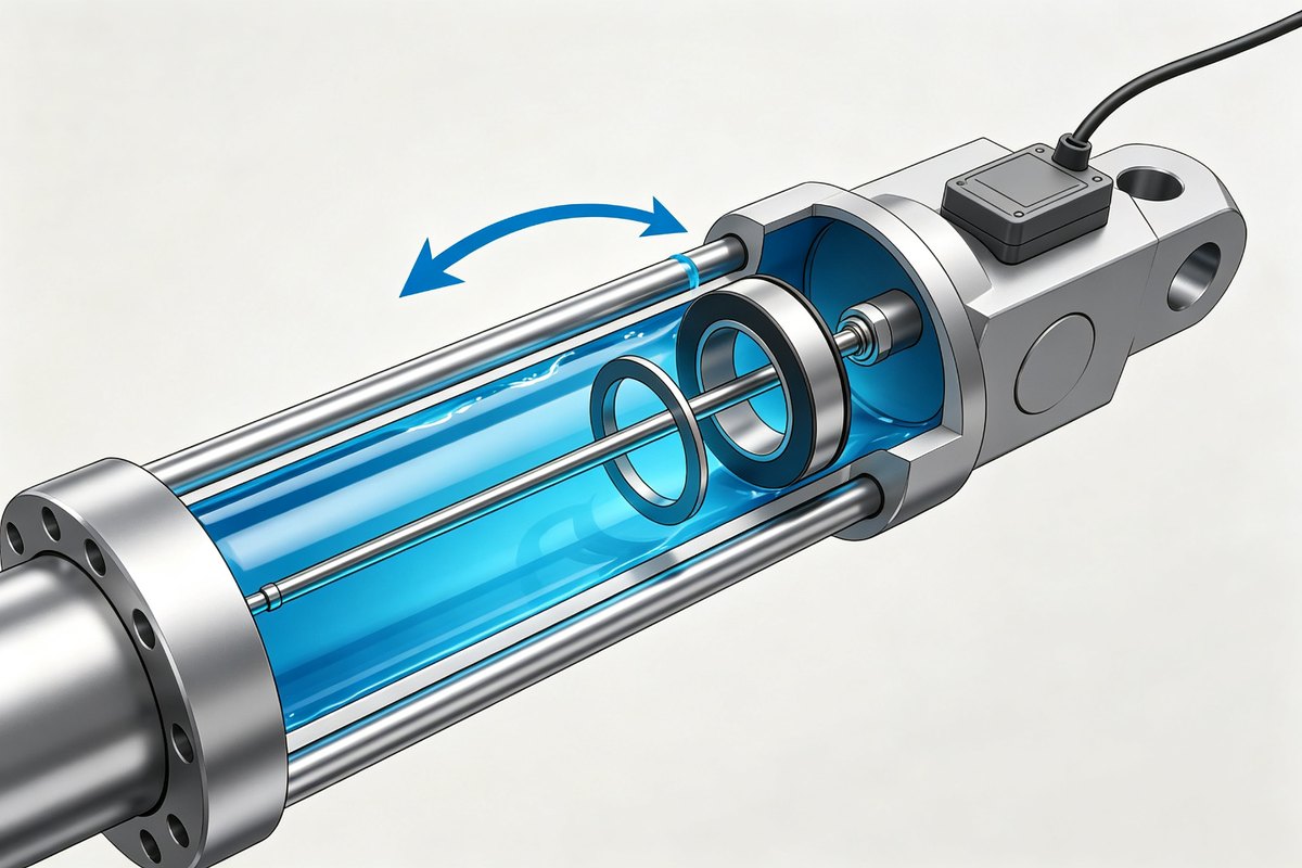
The rod goes into the cylinder; the ring is fixed to the piston. When the piston moves, the ring moves with it, and the sensor times a pulse against the ring to get the position — no contact, no mechanical wear, no seal compromise beyond the rod bore. That is why hydraulic cylinders use magnetostrictive rather than a sliding wiper.
Wiring: analogue four-wire, digital by pin
Outputs come in two families with different hook-ups:
- Analogue (4-20 mA / 0-10 V) — four-wire: a 24 V pair for supply and an independent pair for the signal. Never tie signal minus to 0 V.
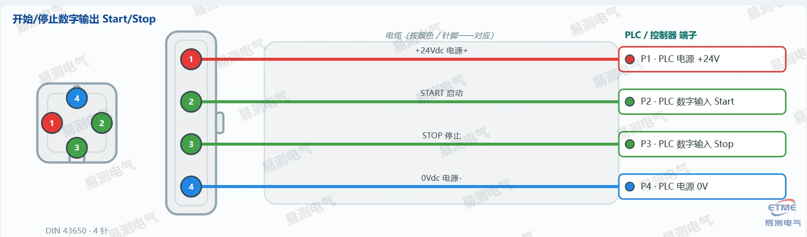
- Digital (CANopen / Profibus / SSI) — follow the series pin table; do not reuse an analogue plug. The DIN 43650, M12, D60 and D70 pin-outs for the Germanjet 12-19 series are all in the wiring reference.
Mounting rules (four)
- The rod must be centred in the cylinder bore — an offset rod rubs and reads badly.
- The ring must be fixed reliably to the piston and travel the full stroke.
- The mounting bore must accept the rod O-ring and keep the pressure rating.
- Route the cable out with a drip loop; on mobile machines add strain relief.
Parameter table (in-cylinder series example)
| Parameter | Typical value | Note |
|---|---|---|
| Stroke | 50-2000 mm | choose with margin |
| Resolution | 0.005 mm | timing-based |
| Repeatability | ±0.001 % FS | clean field needed |
| Output | 4-20 mA / 0-10 V / CANopen / SSI | fix at selection |
| Pressure rating | 350 bar and above | check the series |
| Protection | IP67 / IP68 | sealed variants |
Setting the parameters
- Analogue: zero at the reference position, span at the far position, direction if inverted.
- Digital: node ID and baud first, then PDO mapping, save to EEPROM.
- After setting, run the cylinder slowly end to end and check continuity of the reading.
How to choose a brand
- Proven in-cylinder track record — the rod and seal are the hard part, not the electronics.
- Pressure and stroke range that covers your cylinder without an adapter.
- Local support for commissioning and fault finding.
If the cylinder sensor starts reading badly, go to fault troubleshooting for hydraulic cylinder sensors. The complete pin tables are in the wiring reference.
Frequently Asked Questions
Q: Can an in-cylinder sensor be retrofitted to any cylinder?
The cylinder must accept the rod: a mounting bore through the head with the right seal and pressure rating. Check the cylinder design before ordering.
Q: Which output for a hydraulic cylinder sensor?
Analogue 4-20 mA / 0-10 V for standard cards, CANopen / Profibus / SSI for digital systems. Fix the output at selection.
Related Products
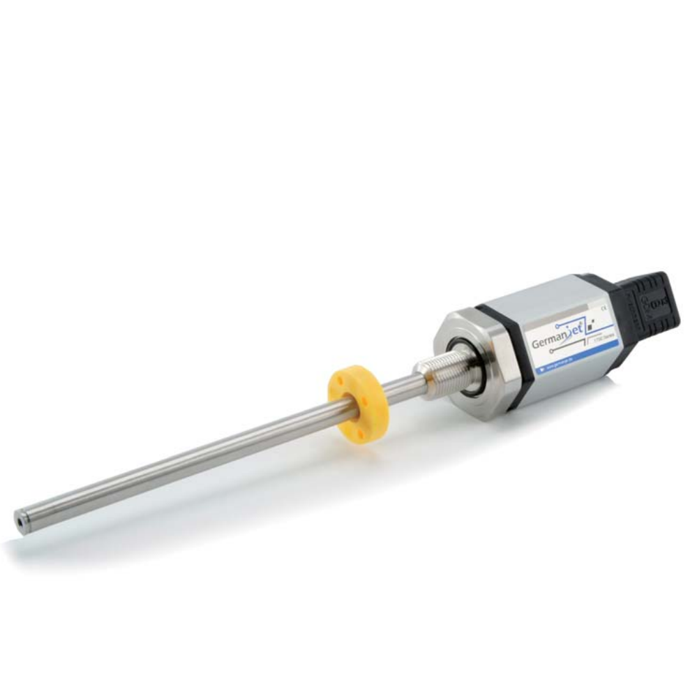
Series 17 Hydraulic Cylinder Integrated
View Product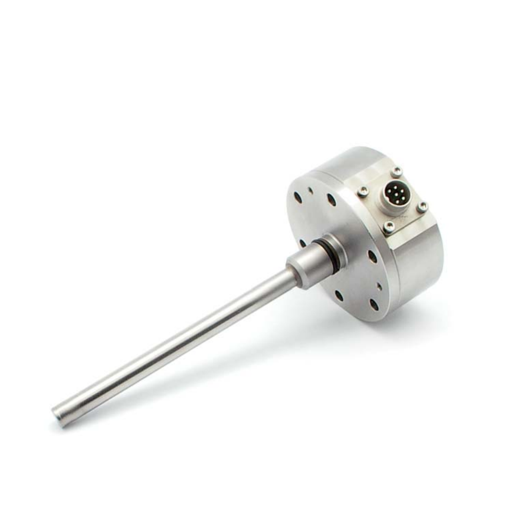
Series 16 Hydraulic Cylinder Built-in
View Product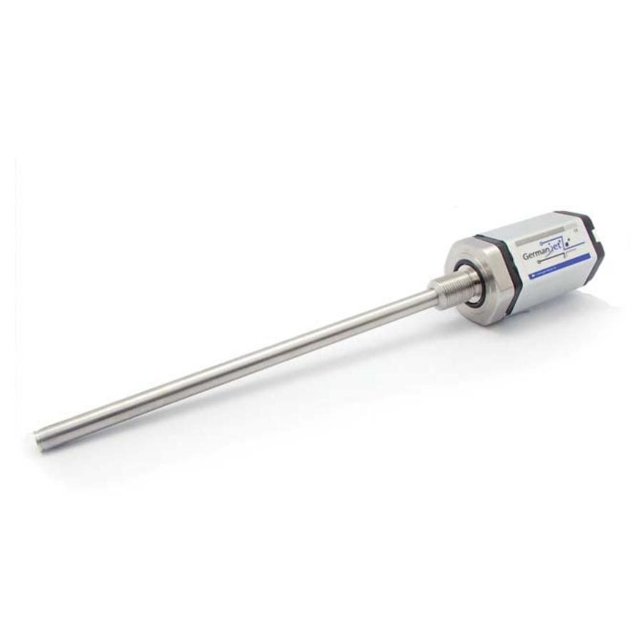
Series 19 H-Type Built-in Cylinder
View Product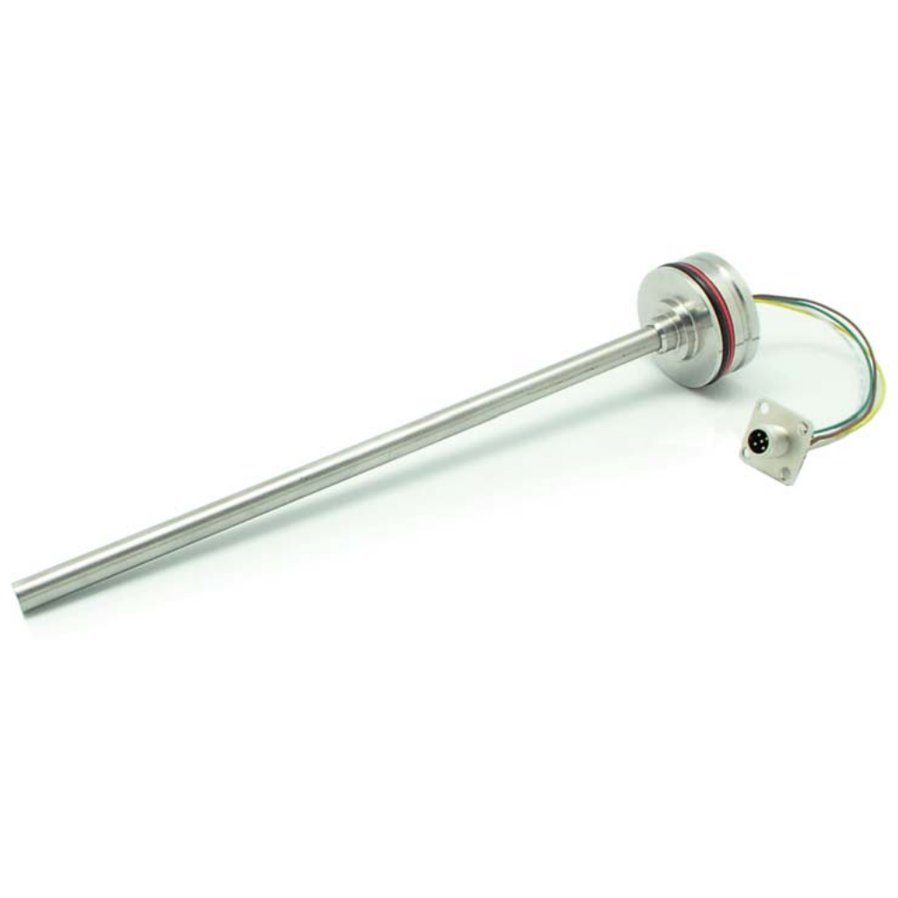
Series 13 Mobile Hydraulic
View ProductRelated Applications
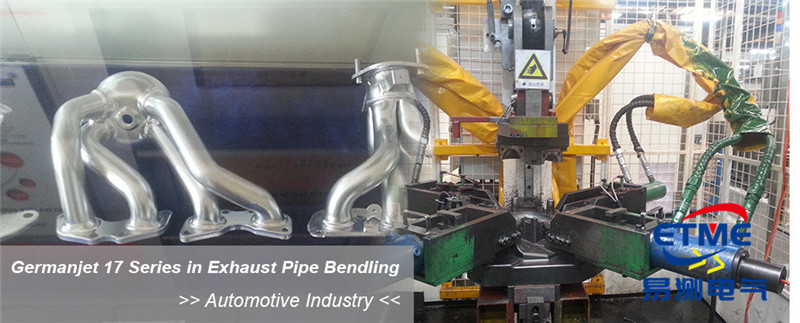
Series 16 Hydraulic Rod Magnetostrictive Displacement Sensor Application Cases
View Details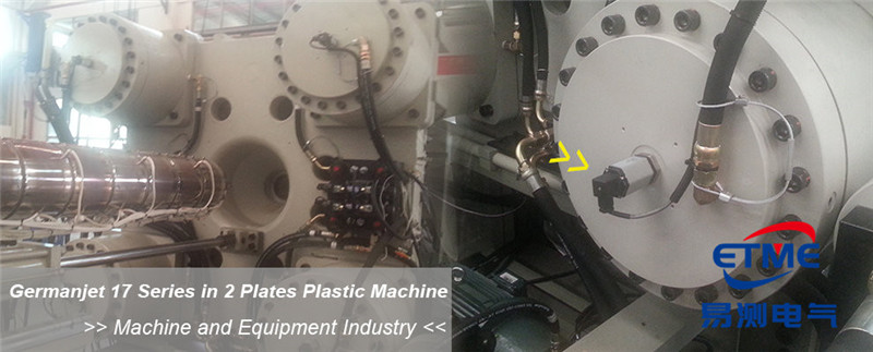
Series 17 Hydraulic Cylinder Integrated Magnetostrictive Displacement Sensor Application Cases
View Details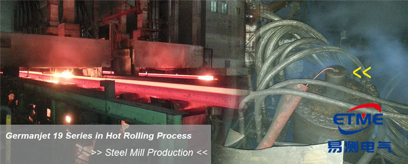
Series 19H Cylinder-Integrated Process Displacement Sensor Application Cases
View Details